Eng-Tips is the largest engineering community on the Internet

Intelligent Work Forums for Engineering Professionals

Understanding test result of 3 winding transformer 1

Status
Not open for further replies.

powerven

Electrical
Feb 26, 2009
4
0
0
MY
Dear Engineers,

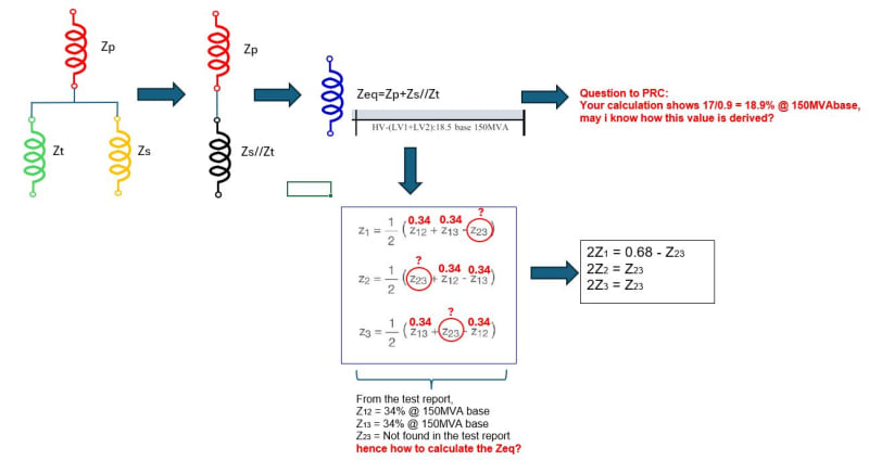
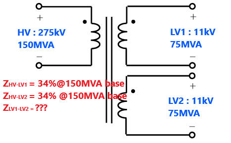
I would like to know how to interpret/understand the test result of a three winding transformer specifically the %Z value, from the diagram below i managed to extract the some of the details, however the details of the %Z between LV1 and LV2 winding is not identifiable.
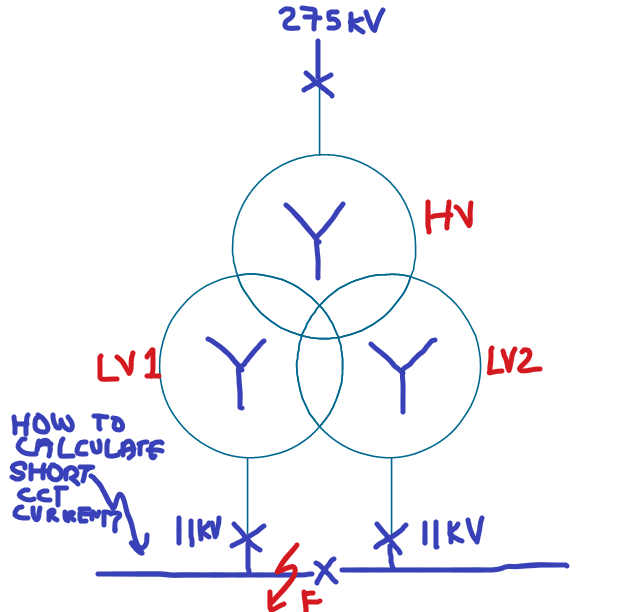
Also i need some guidance to calculate the short circuit current at the LV side which is 11kV when both the LV windings are paralleled. Which %Z value shall be referred?
I have attached the transformer test result and the diagram.
Simple-three-winding-transformer-model-The-inductance-matrix-L-for-the-three-winding_ztn9rv.png

pict--potential-transformer-with-3-windings-transformers-and-windings-vector-stencils-library_usl5qj.png

The Transformer brief detail:
1.) Three Winding Transformer
2.) 150MVA/75MVA/75MVA
3.) 275kV/11kV/11kV

Your input and guidance would be much appreciated.
 
Replies continue below

Recommended for you

I would think both primary-secondary and primary - tertiary impedances would then be in parallel, and you could use standard parallel equations to determine the combined value.

 
Consider the two identical in series for 22 kV and 150 MVA capacity.
Use 22 kV and 150 MVA to calculate the Available Short Circuit Current of the 11 kV windings.
I get 20,053 Amps ASCC for either of the 11 kV windings.
I do find the note "Base 150 MVA" troubling when applied to a 75 MVA rated winding.

The full load current of a 75 MVA winding at 11 kV will be 6818 Amps.
Basing the % imp on a 150 MVA base would imply that the % imp test was done at 13616 Amps. (2 x full load current)
I think that a call to the manufacturer may be in order.


--------------------
Ohm's law
Not just a good idea;
It's the LAW!
 
Assuming HV-LV1= HV-LV2= 34 % as correct ( ie 17 % on 75 MVA base) HV-LV1+lV2 impedance will be 17/0.9 =18.9 % on 150 MVA base. So when both LV1 and LV2 are in parallel, SC current will be based on 18.9 % impedance and 150 MVA base.
Impedance between LV1 and LV2 will be = 2x 0.925 x 18.9 = 35 % on 75 MVA base,

The above constants are from typical similar transformers.
 
Dear PRC,
Referring to your reply , I'm lost in this part:
HV-LV1+lV2 impedance will be 17/0.9 =18.9 % on 150 MVA base.
Please assist.

Thanks
powerven
 
When both the LV1 and LV2 are loaded, the impedance offered by the transformer is 18.9 % on a 150 MVA basis. I have used the thumb rule to arrive at this figure.
 
Dear PRC,

Is there any reference documents which i can refer to understand the calculations which you have shown?
I'm kind lost with that....
Thanks

powerven
 
1996
Giorgio Bertagnolli -Short Circuit duty of Power Transformers –The ABB approach -ABB Transformatori, Legnano, Milano, Italy Ed1.0 Pages 190 -1996, Ed2.0 Pages 190-1998, Ed3.0 Pages 225- 2007
[tt][/tt]
 
Dear PRC,
Is the formula applicable for any type of LV1&LV2 winding arrangement? Is it applicable for LV1 & LV2 axially in stack?

Thanks,

Fouad


Dear PRC,

Referring to your calculation, below are my further queries related to the numerical derivation:

calc_okjfhl.jpg


Your guidance is appreciated.

Thanks
powerven
 
The factors are not derived units but from observing the impedance pattern in similar transformers. You will find Z1 almost zero in this type of transformers.
 
Status
Not open for further replies.
Back
Top