Eng-Tips is the largest engineering community on the Internet

Intelligent Work Forums for Engineering Professionals

Unexplained Voltage across Breaker 1

Status
Not open for further replies.

Arentsch

Electrical
Mar 16, 2009
23
0
0
US
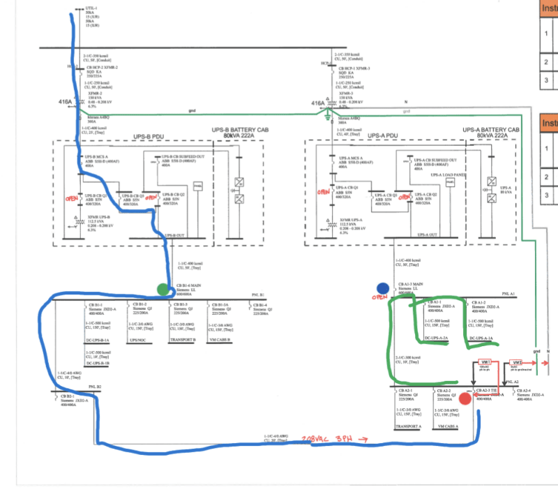
Can anyone suggest possibilities of why we are reading 120vAC across CB A2-3 TIE on the attached one-line diagram? All breakers are closed unless indicated w/ "open". Readings were taken at VM1 and VM2 as shown on one-line. VM1 readings were 120vAC across the line side and load side of CB A2-3 TIE. A-A, B-B, C-C, and all combinations. VM2 readings were 0vAC between line side of CB A2-3 TIE and ground, and Neutral. Thought it might be ghost or phantom voltage, so we tried a solenoid actuated "wiggy" style voltage tester with same results. [URL unfurl="true"]https://res.cloudinary.com/engineering-com/image/upload/v1714505443/tips/S24043014471-1_y0cfgo.pdf[/url]
 
Replies continue below

Recommended for you

Your incoming line voltage is out of phase with your Uninteruptible Power Supply.

--------------------
Ohm's law
Not just a good idea;
It's the LAW!
 
I thought the same thing for a minute but realized the 120VAC reading is phase to phase across the tie breaker. no neutral readings involved. The phases on the line side of tie are completely isolated and are not grounded obviously.
 
The blue line shows power coming to the breaker from the left. One or more of the loads on the green line is connected to neutral. That puts the opposite side of the breaker at the neutral potential which is why you're seeing 120V. Also, your neutral is bonded to your ground which is why you see zero volts. Open CBA1-1, CBA1-2 CBA2-1, and CBA2-2 and you should see your potential clear. I missed the two other branch circuits when I did my mark-up.

Screenshot_20240430-135132_ssl7cf.png
 
Got it! Thank you! I couldn't get my mind around the fact the neutral could make its way back through the load to the phases. Closing the CB A2-3 Tie to provide service to panel A1 and A2 should not be an issue, right? Thanks again!
 
After closing CBA2-3, the neutral path back to XFMR-2 could travel through XFMR-3's neutral wire then through the ground path to XFMR-2 depending on the path of least resistance. Is this a common occurrence with tie switches on 4 wire systems?
 
Yes, I believe that would be correct. There should be no shock hazard normally but if the neutral were ever to become disconnected, one side would rise to the high voltage.

I've never seen a 4 wire system with two parallelable power supplies. This may be a case that requires a 4 pole breaker. Consider installing a 4 pole breaker at position CBA1-3.
 
This is a critical load so customer has two UPS's. However, they will never be paralleled as OEM says "don't". They wanted the redundancy for UPS maintenance and/or failure and for the extended battery period if needed for long outages. I found that the UPS Q3 breaker is 4 pole. They may need to open this breaker also to isolate neutral in this switching scenario.Thanks again @tugboateng for your thorough and accurate responses!
 
If the manufacturer indicates paralleling the UPS's would result in damage, and paralleling is mechanical / electrically possible, some sort of interlock is necessary to prevent a visit from Murphy.

Consider a trapped key system.
 
Status
Not open for further replies.
Back
Top