Continue to Site

Eng-Tips is the largest engineering community on the Internet

Intelligent Work Forums for Engineering Professionals

  • Congratulations waross on being selected by the Eng-Tips community for having the most helpful posts in the forums last week. Way to Go!

Unique GD&T Layout Question

Status
Not open for further replies.

herkyengineer

Mechanical
Nov 19, 2020
4
I am looking for some help/ clarification on how to define the datum structure/layout for a part we are making. See figure attached.

I am trying to control Feature A and Feature B to Datum D. These features need to be near .000 to each other left to right (midplane).
I can relate them to datum D but I don't know how to control them to each other left to right (midplane).
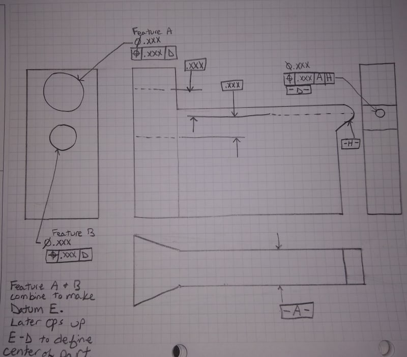
IMG_20201119_091537344_motkiw.jpg

The other thing I can think of is to have Feature A and B be datum targets and define datum E with a position back to datum D.


Replies continue below

Recommended for you

What standard and version are you using, ASME Y14.5 or ISO?

I can relate them to datum D but I don't know how to control them to each other left to right (midplane).

Since they are both held in position wrt to datum feature D, they are held in simultaneous requirements and therefore the tolerance zones for "feature A" and "feature B" are fixed at basic relative to each other. The issue there is that datum feature D alone leaves free your rotational DOF around D's axis and therefore the tolerance zones for these features may rotate together relative to A. Holding them in Position to |A|D| would be a remedy for that.

Its not clear to me what you're trying to use as datum feature H. Is it the radius? Or are you trying to specify a datum target? Or is it the angled face shown? Regardless this seems questionable to me.

Note your datum features should be driven by the function/assembly of the part, not just what DOF they may or may not constrain or you think you need to constrain. I would analyze the features you are choosing as datum features to ensure they reflect this.

The other thing I can think of is to have Feature A and B be datum targets and define datum E with a position back to datum D.

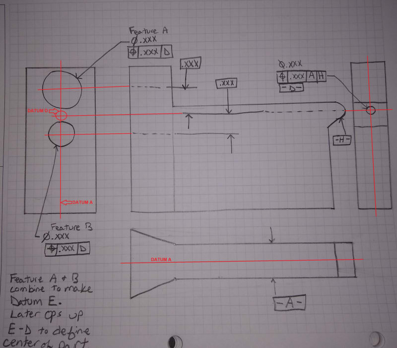
This isn't how datum targets work. Datum targets are by definition at basic location/orientation.
 
Your drawing is confusing.
I understand it's intentionally incomplete to protect sensitive information.

It's unclear what your datum [H] is, but if it is legit, you can position your features A and B wrt datums [A] and [D]
(There are different possibilities, depending on parts function)
That will control their left-to-right location.

IMG_20201119_091537344_2_rzosl3.jpg


"For every expert there is an equal and opposite expert"
Arthur C. Clarke Profiles of the future
 
chez311

We are using Y14.5-2009.

I can add |A|D|. H is a radius on the raw stock that we are relating to.

Would it be ok to have feature B be related to Datum A and D but call out its dimension from Center of Datum A? shop floor cares more about that then its location to Datum D.

Could I refine the frames on Features A and B to something like this:
|POS|.xxx|A|D|
|POS|.xxx|A| where this is smaller than the above zone?

We do use the features A and B as well as Datum D to hold the part for the next OP (-D- is rotational center and Features A and B are used as an offset center).
 
Would it be ok to have feature B be related to Datum A and D but call out its dimension from Center of Datum A?

As long as your features have basic location/orientation back to all applicable datum features, as well as basic location/orientation between datum features it doesn't matter where they originate.

H is a radius on the raw stock that we are relating to.
[...]
shop floor cares more about that then its location to Datum D.
[...]
We do use the features A and B as well as Datum D to hold the part for the next OP

Sounds like the shop floor is dictating the design of this part, not the actual intended function and/or customer requirements. Obviously no design work should occur in a vacuum as a perfectly designed part that can't be produced is of little use, however ignoring functional/assembly/customer requirements in favor of what your manufacturing team desires is a mistake. Depending on the application it could be a very costly mistake - in the same manner that a part that can't be produced is of little use, a part that doesn't function (or doesn't function consistently due to allowable variation) is also of little use.

Are any of these features (especially H) functional surfaces? I am skeptical you actually desire the implications of using H as a datum feature (assume perpendicular to A is z -> rotational DOF w is free and non-FOS partial cylindrical simulator).
 
The features I want to use don't exist until later in the machining process.

H is a forged surface and the next operation puts a hole that we want centered in the radius.

They are depicting how they want to see the print but I trying to layout my print so that it makes sense to them and relays the information I want it to.
 
So this is an in process drawing or the final print?
 
in process. The part has 10 machining operations.

This is the 1st op that sets up the datum features used to fixture the other ops.
 
Hi, herkyengineer:

Is feature for datum D a blind hole or a through hole? You are not supposed to use this feature as a primary feature unless it is a very deep hole or through hole.

Best regards,

Alex
 
Status
Not open for further replies.

Part and Inventory Search

Sponsor