BiomedicalEngineering
Bioengineer
Hi everyone,
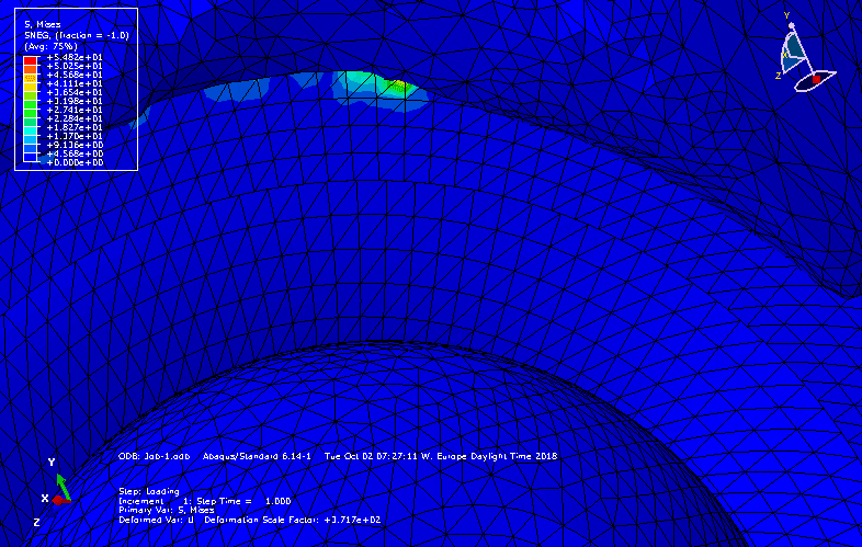
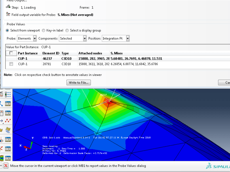
I am doing a FEM-analysis in Abaqus of a human hip with an implant. However, when I apply a static load of 2000N (which occurs during walking) I obtain a high stress (400 Mpa) for a few elements at the interface between bone and implant(see figure top left
 ). The majority of the elements show a realistic result (7 Mpa). I can't figure out why these elements have a value for almost 50x as high. If anyone has experiece with this or knows what could solve this issue, it would really help me.
Thanks in advance.
Additional info model:
- I use knot tying as a constrain between the implant (a cup) and the bone
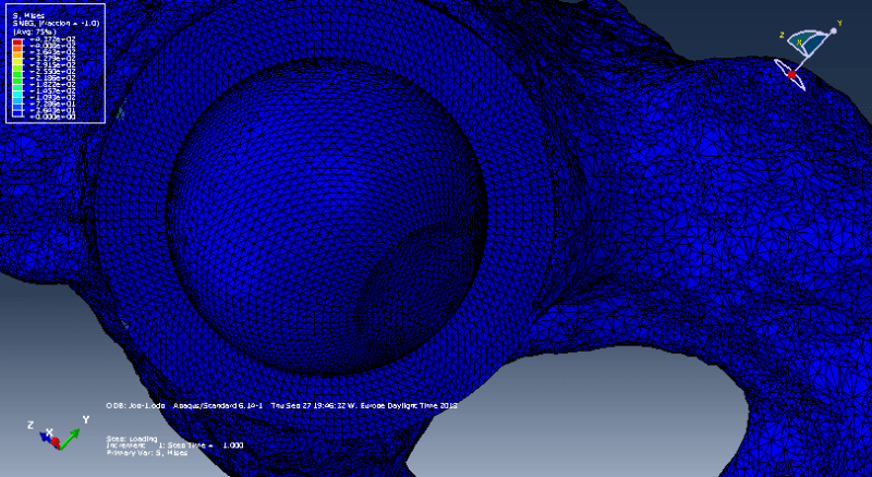
- I apply the load to the spherical femoral head (see image)
- The implant should exactly fit in the bone since I substracted the geometry of the implant from the bone.
- The bone is obtained from Mimics and is already meshed (thus becomes an orphan mesh in ABaqus). Therefore I can not change the element type.
- Some warnings were given:
*14872 elements are distored. (even if I increase the elements up to 1 million in Mimics and thus the elements become really small, these elements are still distorted)
* some elements (about 10) are not tie knotted since the distance is too big. I think this could be since I selected a bit too much elements which were not in range.
* The modified tetahedral elements are incompatible with the regular tetahedral elements if they share the same node.
* The ratio of the maximum incremental adjustment to the average characteristic length is 2.94555e-02 at node 404 instance cup-1 on the surface pair (assembly_cup-1_cupouter,assembly_reamedpelvis2-1_acetabulum2).
I am doing a FEM-analysis in Abaqus of a human hip with an implant. However, when I apply a static load of 2000N (which occurs during walking) I obtain a high stress (400 Mpa) for a few elements at the interface between bone and implant(see figure top left
Thanks in advance.
Additional info model:
- I use knot tying as a constrain between the implant (a cup) and the bone
- I apply the load to the spherical femoral head (see image)
- The implant should exactly fit in the bone since I substracted the geometry of the implant from the bone.
- The bone is obtained from Mimics and is already meshed (thus becomes an orphan mesh in ABaqus). Therefore I can not change the element type.
- Some warnings were given:
*14872 elements are distored. (even if I increase the elements up to 1 million in Mimics and thus the elements become really small, these elements are still distorted)
* some elements (about 10) are not tie knotted since the distance is too big. I think this could be since I selected a bit too much elements which were not in range.
* The modified tetahedral elements are incompatible with the regular tetahedral elements if they share the same node.
* The ratio of the maximum incremental adjustment to the average characteristic length is 2.94555e-02 at node 404 instance cup-1 on the surface pair (assembly_cup-1_cupouter,assembly_reamedpelvis2-1_acetabulum2).