Hi all,
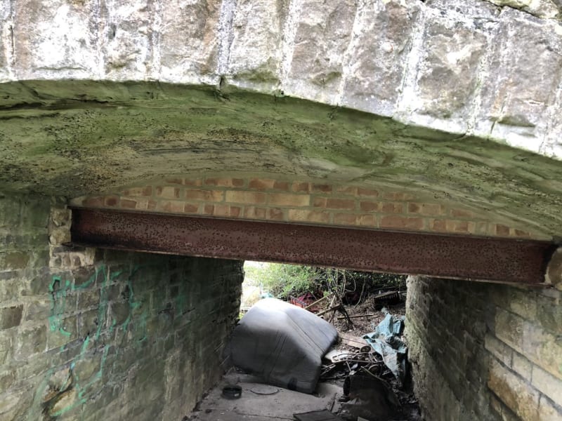
I am currently looking at an unreinforced concrete arch bridge, which I believe developed some transverse cracking in the past and therefore has been strengthened with steel beams and brick diaphragm walls @ 1m c/c as shown on the photograph below. The transverse section of the structure effectively looks similar to a steel beam and infill slab bridge, however, the unreinforced arch, which acts as the infill slab must transfer the loads onto the steel beams somehow.
This article gives some ideas and refers to UK departmental standards (CD 360 is the current version of the standard), however, the standard only deals with reinforced concrete.
My idea is that the arching action in this concrete infill slab can be checked by imagining a mass concrete slab within this 'infill' slab when looking at it in cross-section with the rest of the concrete on the intrados being non-structural.
Alternatively, I can imagine two compression struts inside the arch pushing the beams apart.
Could you please advise on how'd you approach this?