Eng-Tips is the largest engineering community on the Internet

Intelligent Work Forums for Engineering Professionals

Unreinforced Masonry Allowable Flexural Tension Stresses Table 2

Status
Not open for further replies.

zurch1818

Structural
Feb 16, 2015
24
0
0
US
I typically analyze existing concrete/steel structures. However, on occasion, I'm tasked with analyzing an existing brick/masonry structure. I'm hoping someone can provide some feedback on this particular table.

Unreinforced_Flexural_Tension_drh6th.jpg


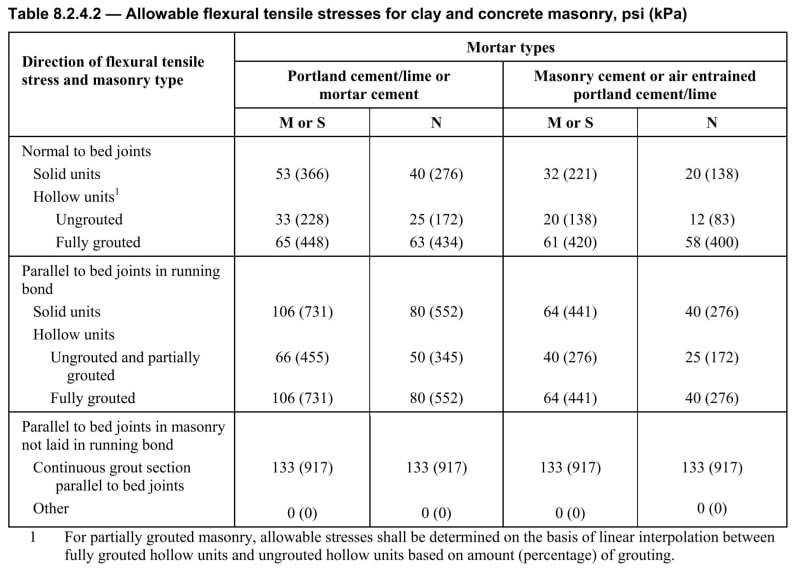
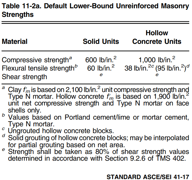
More often than not, I am using the first section, normal to bed joints. However, I am in the process of building an elaborate spreadsheet as a way for me to better understand masonry design to see if I can possibly gain more capacity since I can tell a lot of these really old brick walls have been around for 100 years and I can tell they didn't consider current code in their design, so they shouldn't be standing (on paper).

I'm trying to figure out what the other two categories even mean. It seems they are for walls spanning horizontally, but I am not sure. I don't have any idea when "continuous grout section parallel to bed joints" would ever apply. Maybe some sort of unreinforced lintel or grouted clay tile (which obviously isn't used anymore)? I don't know how else you would get grout parallel to the bed joint.

Also, does anyone have a good reference for engineering historic brick walls? For engineering properties, it seems I should be able to assume that it is comparable to a solid CMU wall of the same nominal dimension. However, this gets a little tricky with multi-wythe brick walls. If anything it seems the triple-wythe brick wall should be a little bit larger than a solid 12" CMU wall.

Lastly, I'm not sure if historic brick has holes in it or not. I'm guessing this will change the Anet a little bit but it will also change the adhesive anchor design. It becomes difficult with Hilti when they say the wall needs to be 13" thick but a triple-wythe wall should be less than this. Thanks for any insight you can give me.
 
Replies continue below

Recommended for you

zurch1818 said:
I'm trying to figure out what the other two categories even mean. It seems they are for walls spanning horizontally, but I am not sure. I don't have any idea when "continuous grout section parallel to bed joints" would ever apply. Maybe some sort of unreinforced lintel or grouted clay tile (which obviously isn't used anymore)? I don't know how else you would get grout parallel to the bed joint.

The other two categories (Tensile Stress Parallel to Bed Joints) are for masonry that is spanning horizontally. For masonry not laid in running bond (typically a stacked bond pattern), the head joints get ignored, but you can consider a continuous section of grout if it is there. Take a look at TEK 14-07C, Allowable Stress Design of Concrete Masonry Based on the 2012 IBC & 2011 MSJC, which says:

"For assemblies spanning horizontally between supports, the code conservatively assumes that masonry constructed in a bond pattern other than running bond cannot reliably transfer flexural tension stresses across the head joints. As such, the allowable flexural tension values parallel to the bed joints (perpendicular to the head joints) in these cases are assumed to be zero. In cases where a continuous section of grout crosses the head joint, such as would occur with the use of open-ended units or bond beam units with recessed webs, tension resisted only by the minimum cross-sectional area of the grout may be considered."​

Structural Engineering Software: Structural Engineering Videos:
 
What do others do when the code itself states that it's conservative to neglect the tension component in the stack bond scenario?

I have a horizontally spanning breeze block wall in stack bond that is spanning between masonry plasters. I want to believe that the stress at the head joints behaves just like a vertically spanning wall bed joints in my scenario. Especially since my wall will be constructed tight between my masonry plasters and would induce additional compression in the horizontal direction under bending.

I don't see any difference in this scenario in the horizontally spanning wall and a vertically spanning wall. If it helps you to visualize, my wall blocks are the 12"x12"x4" nominal "flower" blocks, there is no difference in joint size based on the orientation of the block itself.

My gut is saying even though I'm spanning horizontally, my assumption of behavior is valid in this particular case. I'm curious what others would do here, but I'm leaning to designing my horizontal wall using normal to bed joint values for the allowable mortar stress.

Sorry if this is a thread hijack, but I have been staring at this table today trying to figure out why it gives a zero value and why I can't just treat it as a bed joint in my case.
 

I have never done any load bearing structure, but now I have to learn it for a project. The link you provided, does it apply to it? And could you guide me about which American code applies and where can I get some examples for reference?
 
Also, does anyone have a good reference for engineering historic brick walls? For engineering properties, it seems I should be able to assume that it is comparable to a solid CMU wall of the same nominal dimension.

It's not specifically a reference, but just use ASD method for solid masonry. It's a similar calculation but without rebar. It's probably what you're talking about.

For the strength values, check out ASCE 41-17 table 11-2a and that particular chapter of code.

Screenshot_2024-01-21_131228_dtva9h.png


The flexural tensile strength they have is actually a bit higher than I'd expect, but it's in an authoritative publication, so I see no reason not to use it.
 
Rhoadies said:
I don't see any difference in this scenario in the horizontally spanning wall and a vertically spanning wall.

This is not true since head joints are significantly harder to construct than bed joints. Quoted from the article:

"The reason head joints typically have lower bond strengths than bed joints is related to the orientation of the mortar joint when the walls are constructed. In running bond masonry, the horizontal mortar joint is easy to place with full joints. Also, the bed joints are under compression when the wall is laid up due to the masonry's weight. Head joints are formed by buttering the end of the units with mortar and shoving them into the adjacent units. Unlike bed joints, they are not under compression. With large masonry units, head joints are more difficult to fill than bed joints and therefore may not be filled completely. For these reasons, there is generally much lower bond across head joints than across bed joints."

Also, an NCMA article shows some test results comparing running and stack bond walls spanning horizontally that unreinforced stack bond has about 40% the capacity of running bond. Stacked bond is also required to have horizontal reinforcement equal to 0.00028 times the cross-sectional area. I would stick to using the code prescribed unreinforced strength of 0 psi and rely on bond beams or reinforcing to span horizontally.
 
Status
Not open for further replies.
Back
Top