Continue to Site

Eng-Tips is the largest engineering community on the Internet

Intelligent Work Forums for Engineering Professionals

  • Congratulations KootK on being selected by the Eng-Tips community for having the most helpful posts in the forums last week. Way to Go!

Unusual Moments in Simply Supported Frame in SAP2000 1

Status
Not open for further replies.

NikolayK

Structural
Jun 21, 2020
3
Hi Engtips community,

I am currently trying to model a 6 storey structure in SAP2000 and have applied the following steps:
1. Drawn one-storey version of my model in SAP2000. Steel Frame and Concrete Slab.
2. Applied Auto Frame Meshing for Frames and Areas.
3. Applied Loads using the Uniform Function.(Uniform to Frame doesn't seem to fix it either :()
4. Released Moment 2 and 3 at both ends of frames.
4. All other paramaters kept as standard (i.e. end length offset, Insertion Point etc.)

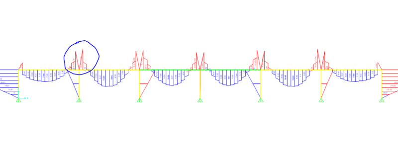
When I run the model, I get an unusual moment occurring at the junctions of the beam and the column (See attached Photo).

To me this doesn't look right. I have tried replicating the model with simpler scenarios than my building and I still get the same effect. This effect runs in both the x and y directions

Can someone please help me with this issue, as I believe it is understating the true moment occurring. Am i wrong in assuming the moment in a simply supported structure will be WL^2/8 on all spans?

Your help is valued greatly :)
SAP2000_Issue_gcyyn8.png
 
Replies continue below

Recommended for you

You have a slab using shell elements I'd bet?

Change it to a membrane.

What you are seeing is typical of an axial coupling occuring between your beam and a shell slab. The slab is acting as a flange for the beam, carrying axial bending loads. This interaction is not realistic and inadvertently stiffens your response. Changing it to a membrane will get rid of the effect.
 
This might also be happening because of beam insertion point. If so, this behavior will vanish if you assigned beam insertion point to centroid.
 
I've seen this often before. You've got a plate / shell element and beam elements at the same spot. Each point of discontinuity in the moment diagram is where the beam connects to the slab and some moment gets transferred between the two elements (beam and plate/shell).

This isn't very significant at mid span because the beam is significantly stiffer than the slab. But, at the end of a simply supported beam, the plate/shell elements want to establish a moment continuity between spans. So, that's what the beam gets some negative bending. But, at the very end of the beam (where the moment end release is) there can be no moment in the beam, hence it drops to zero.

What is the purpose of modeling the slab? Agent 66's suggestion of switching to a membrane slab is a good one if you are relying on the slab only as a lateral diaphragm, and not for gravity design of a concrete slab system.
 
Thanks Agent666,Blackstar123 and JoshPlumSE for your replies!

I have verified that all the beam insertion points are all acting at the centroids.

I have tried using a membrane however as noted by JoshPlumSE, I need to model the gravity design of the slab and its interaction with the steel frame. The results produced by this were negative BMD's as theory would suggest however the deflection was not correct as there is no stiffness in between mesh's of the slab.

The purpose of the modelling is just to model some simple loading scenarios on a symmetrical concrete core - steel frame - concrete slab building and design the steel members and thickness of concrete to be capable of taking the bending moment(ULS) and within the deflection limits (SLS).

Another method tried is to modify the joints with their constraints however the same result was found.

When running this in Robot, a similar result was found at the ends. Is the result I am getting incorrect?

 
NikolayK said:
Is the result I am getting incorrect?

It's correct from a purely elastic analysis standpoint. But, I'd argue that it's incorrect from a design standpoint. Some thoughts on this:
1) Is this a composite beam floor system? If so, what mechanism (shear studs?) are you using to transfer horizontal shear between the flange of the steel beam and the concrete slab? If you don't have a mechanism to do that, then you shouldn't rely on composite behavior.

2) Even if this were a composite beam, it is very odd to assume negative moments can develop in a simple supported composite beam. Even for moment frame beams that have a slab over them, we don't usually assume composite behavior to stiffen the behavior of the beam.

3) What happens in reality? My guess is the beam is loaded by dead load and slab dead and such BEFORE the slab has a chance to fully harde. In which case, that load doesn't distribute the way you're seeing. You can make an argument about what happens for load applied AFTER the slab hardens (such as live load).

Personally, I think you might have to consider to different "models". One where the model is geared towards analyzing the slab and one where the model is geared towards analyzing the beam.
 
Johnie134 -

I'd like to encourage you to contribute in a more meaningful way than plugging another program. There's nothing inherently wrong with mentioning another program, of course. Unless you are associated with that company in a way that would violate Eng-Tips community guidelines for pushing a product.

However, when you do mention another product, please try to do so in a useful or meaningful way. The issue here is related to the interaction between his plate elements and his frame elements. So, suggesting that he eliminate the plate elements and just do a pure 2D frame analysis (with any program) would be reasonable. Just throwing out the name of another program does little to advance the discussion.

Note: I work for SAP2000's parent company CSi. Before that I worked for one of their competitors (RISA) for about 16 years. So, I am far from an unbiased observer. But, I try to make that clear when offering any advise that might be skewed by my background.
 
JoshPlumSE, there are better alternatives than sap & risa. Very interesting that you talk about community guidelines. are you maybe violating them by referring to Sap2000? Please get serious.
 
Guys me and my employees use to work with the following software packages:
ADC
RFEM and RSTAB
SPACE GASS
ENGISSOL
AUTOCAD
TEKLA
Do I commit a violation by posting them?!
 
Johni3134 said:
Very interesting that you talk about community guidelines. are you maybe violating them by referring to Sap2000?

Johnie134 -

This is a statement of bias on my part. I'm not plugging either program. Just letting people know that I'm not an impartial observer on the subject of analysis programs.

You should feel free to talk about any programs you wish. Provided that you're not receiving some benefit from advertising / plugging them.

Now, I (and others) have respectfully pointed out that when you do mention your favorite program, you should do so in a manner that contributes in a meaningful way to the discussion in the thread.

Can you explain how your original post "tried using engissol 2d frame analysis app?" helps anyone in this thread? Unfortunately, posts like yours are viewed with suspicion. Others in the engineering software field (even Bruce, my former boss at RISA) have signed up with misleading names in order to promote their products. RISA was involved in a long, drawn out lawsuit related to something along these lines when I first started there. As I understand it, the owner at the time (Bruce) had an account that he used to hype up RISA's software. He was caught doing it by a competitor who later sued.

Now, if Engissol has a feature that can help with the continuity / connectivity between frame and plate elements, then by all means, please enlighten us. But, I'm certain that a comment like "tried using engissol 2d frame analysis app" does little to advance the knowledge base of this group or help the OP with his / her original question.

 
Hi Josh! Woww you must have plenty of time to write such a long story!! Anywyay, I suggested engissol as it is very easy for beginners and can help you get moment diagrams on continuous beams. This is a personal suggestion. I don't work for engissol. i'll consider asking them for a promotion fee, according to your post, lol
 
Johnie134 said:
I suggested engissol as it is very easy for beginners and can help you get moment diagrams on continuous beams.

Actually, your post wasn't nearly so informative or helpful. That was my whole point.

Note: I'm not asserting that you work for Engissol (although I thought it was a possibility). Rather, I was explaining why the Eng-Tips site is suspicious of posts like the one you made.

Overall, I'm really just trying to help you understand the expected behavior on Eng-Tips. Those of us who have been here awhile do that so you newer members can better understand the rules. We want you to stay so that you can continue to contribute and not get kicked off for silly misunderstandings that could easily be avoided.... by making sure your posts contribute in a meaningful way.
 
TEKLA
Do I commit a violation by posting them?!

No, not here, but when you posted in someone's thread asking specifically about TEKLA, you instead pointed them to your go-to program. I've yet to see any data or any other expansion on any of your postings, which rarely exceed one extremely brief sentence. "You should try ****" is not a useful answer, particularly if the OP isn't asking for an alternative.

TTFN (ta ta for now)
I can do absolutely anything. I'm an expert! faq731-376 forum1529 Entire Forum list
 
It's not spying johnie134, it's intelligent readers (engineers) reading posts and seeing you mention xxxxxxx so often and often with little connection to the posts that you're coming across as a shill. Have you not noticed your repetitive posts about xxxxxxx are now being expunged? I'd take the hint that it's not welcome.

Keith Cress
kcress -
 
itsmoked , are you IRstuff's lawyer? That is getting really funny!
 
Status
Not open for further replies.

Part and Inventory Search

Sponsor