Eng-Tips is the largest engineering community on the Internet

Intelligent Work Forums for Engineering Professionals

Unusual rear multi-link suspension 1

Status
Not open for further replies.

Despo8

Automotive
Mar 9, 2020
9
0
0
GB
Below is a Mercedes rear multi-link (EQA I believe). I say it's unusual as it's clearly a multi-link with two lower links, one upper and a longitudinal, however the longitudinal seems to be very thin piece of sheet metal that's fixed on the knuckle side.

First of all, does this not constraint the system to 0 DOF with the inboard fixing on the longitudinal link? Has anyone got any experience with this layout and can comment on advantages an disadvantages?

D241703_ubhvek.jpg
 
Replies continue below

Recommended for you

Lots of modern vehicles use something like this. Ford Focus "control blade" suspension was an early example, but VW Golf Mk5 and onward (those which use multilink IRS and not a twist-beam axle), 2016-on Honda Civic, are the ones that I have some familiarity with.

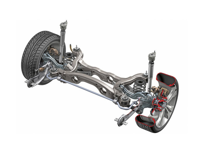
The trailing link locates the knuckle fore-aft (X) and in side-view (X-Z plane) rotation (think "trailing arm" but in side-view only - the trailing link is the one that absorbs braking torque). It does not locate the knuckle in toe or camber or laterally - that's the job of the lateral links. The trailing link is intentionally flexible in the directions that it does not serve a locating function (or taking up braking torque). Sometimes the trailing link is (almost) a flat piece of sheet metal to encourage flexing in the directions that it needs to flex. Sometimes it's attached to the knuckle with bushings that allow some "give". It is not over-constrained, because the trailing arm is designed to flex in the directions that it needs to.

The two lower links locate the knuckle in toe. The rear one is much longer than the front one, because remember, the knuckle is rotating in the X-Z plane, so with suspension up-down movement, the rear link travels much further up and down than the forward link does. Roughly speaking, in top view, the chassis-end pivots of the rear lateral link, the front lateral link, and the trailing link are in line. Usually the front lateral link will be a little shorter than this, in the interest of encouraging toe-in with both bump and rebound travel, which is the same as saying toe-in in roll. (Roll understeer)

The two lower links are pretty close to parallel in top view. This means the trailing link chassis-end bushing can be soft, because slight fore-aft movement of the knuckle (due to bushing deflection from bump impacts, or from braking) produce almost no toe change of the knuckle. This is better for separating the NVH forces from the handling forces. The lateral-link bushings can be stiff with little impact on NVH.

That the trailing link is very short, means there is a lot of anti-dive (in the rear, anti-lift) in braking. Because the forward drive torque reaction is not done in the knuckles (whether it's front-drive, or rear-drive with the diff bolted to the subframe), this doesn't lead to excessive anti-squat during acceleration.

The upper link just has to provide the desired camber in response to bump travel (or body roll).
 
I am very familiar with that style of suspension, from 1997 onwards. We had 3 lateral links to control camber and toe, and a longitudinal link to react the longitudinal forces.

It's a very nice suspension to work with, the main conceptual difficulty is getting the control blade/front bushing soft enough to allow the hub to steer, without buckling or durability issues.

One big advantage is that the natural location of the blade means the mount fits nicely into the chassis rail. That's good for impact harshness and road noise.

It's an orthogonal design, meaning that if you adjust one thing on it it doesn't upset everything else, unlike a double wishbone.

Cheers

Greg Locock


New here? Try reading these, they might help FAQ731-376
 
Thank you both for your inputs very useful as you clearly have experience with these.

So the blade I can imagine being very flexible in the global Y (translation) and also around the Z (rotation) and X (rotation) axes, but a lot stiffer around Y (rotation) axis. Wouldn't this Y rotation induce a lot of bending moment during suspension vertical movement? I can imagine that during bump it'll essentially try to rotate the knuckle forward.

@BrianPetersen can you elaborate on the necessity for the two lower lateral link to be unequal length? Does the long rear and short front allow the knuckle to naturally rotate forward around Y and deal with the above issue I stated?

@GregLocock Does accurate analysis of this suspension both kinematically and compliantlly require flex bodies of the control bade, or can you get away with some assumptions/shortcuts?
 
I split the blade into 3 rigid links joined by bushings which matched the FEA of the blade. I didn't use flex bodies but could have done so, at a cost in processor time.

The rear arm is longer to give the right bump steer.

The front bushing design accommodate any excess stiffness of the blade, its only serious job is to react the longitudinal forces, it can be soft in all the other directions, and to be honest isn't all that stiff even in longitudinal (probably of the order of 300 N/mm). I think it snubs pretty quickly though , probably around 6mm.


Cheers

Greg Locock


New here? Try reading these, they might help FAQ731-376
 
Are there any parasitic rates present with wheel travel? I imagine the torsional around global Y is soft on that front bush?

@GregLocock since you mentioned it, how is the snubbing distance determined? Is it essentialy a knee-point between impact forces and braking forces? So for low stiffness (300N/mm) want more snubbing, and vice versa
 
I'm going to presume by "parasitic rates" you mean that there is a "spring rate" imposed upon the actual spring force, which is due to the forces taken to deflect the various bushings and links. If this is what you mean, then certainly there will be some effect.

The trailing arm does rotate around the forward (chassis-end) pivot with suspension movement, along with the entire knuckle. It's doing so by deflecting the elastomer in the bushing. But, so are all the other bushings, because that's how they work nowadays. Modern suspension bushings operate by deflecting the elastomer away from some nominal at-rest position, and that takes force to do.

The trailing link in particular with this design, may be designed to accommodate camber change by twisting along their length, and accommodate toe change in the spindle by bending in top-view. The magnitude of these forces ... is going to be highly application specific.

All modern suspension bushings in automotive applications operate using elastomer deflection, not rolling-element bearings, not sliding-contact. That's why we no longer need "grease jobs"!

This type of suspension does have a lot of parts, and a lot of bushings, relative to some other designs (e.g. my car, which has a twist-beam axle). But, evidently, the manufacturers who use the multi-link design consider the ride and handling benefits from NVH isolation and better toe and camber control, to be worth the higher cost.
 
Ok so the knuckle rotates with the longitudinal arm around the front bush because the other 3 lateral links allow it to rotate without any internal bending?

And what would be the difference between this and a classic 4 link suspension, so replacing the longitudinal link knuckle side fixing with a spherical. I'm guessing that wouldn't work because it doesn't control caster during braking?
 
The three lateral links (and their bushings) twist with suspension movement in order to accommodate the trailing arm motion. You will note that the upper of the three lateral links has a narrow cross-section, because it's meant to perform a lateral locating function, not a torsional locating function. If it twists as the suspension moves up and down, that's OK. It need not be torsionally rigid in order to perform its required function.

Define what you mean by a "classic 4 link suspension" ... show me a picture.

With this suspension design, the trailing link has to connect to the knuckle in a way that transmits torque. If there was a single ball joint at that location, then the suspension would require one more link in order to guide the knuckle in the side-view rotation direction (X-Z plane). This then becomes a 5-link suspension. And, there have been some. The single upper lateral link can be replaced with an A-arm, or with two diagonal links. There's lots of ways to do this.
 
Status
Not open for further replies.
Back
Top