Continue to Site

Eng-Tips is the largest engineering community on the Internet

Intelligent Work Forums for Engineering Professionals

  • Congratulations waross on being selected by the Eng-Tips community for having the most helpful posts in the forums last week. Way to Go!

Unwanted bubbles in the system! 3

Status
Not open for further replies.

xhuydo

Mechanical
Jan 18, 2017
7
Thank you for taking the time and reading my post. I very much appreciate your help.

I am getting bubbles into my pipe system and wanted to know how they are forming and what I can do to remediate.

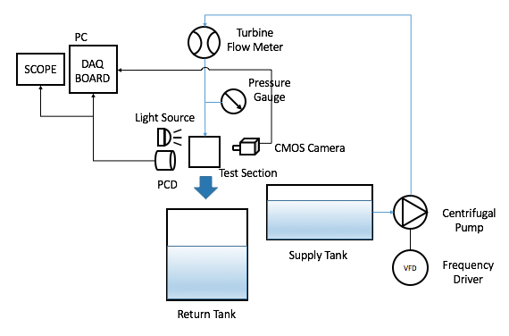
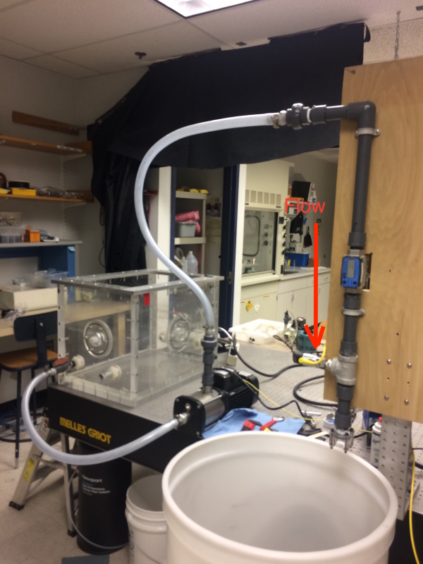
The flow begins at the a reservoir holding water that is open to the atmosphere. Water flows from the bottom via a gated valve and into a centrifugal pump. The flow is directed up and then down. The flow passes turbine flow meter, pressure gauge, and exits from an acrylic nozzle. The plumbing consist of 3/4" ID plastic tubing, and 1" ID PVC. The nozzle has a 1/5" square exit. The nozzle attaches by a mount. The mount screws onto a threaded PVC adapter and then nozzle is essentially clamped on.

IMG_1143_mdx9h4.jpg

IMG_1142_np04yy.jpg


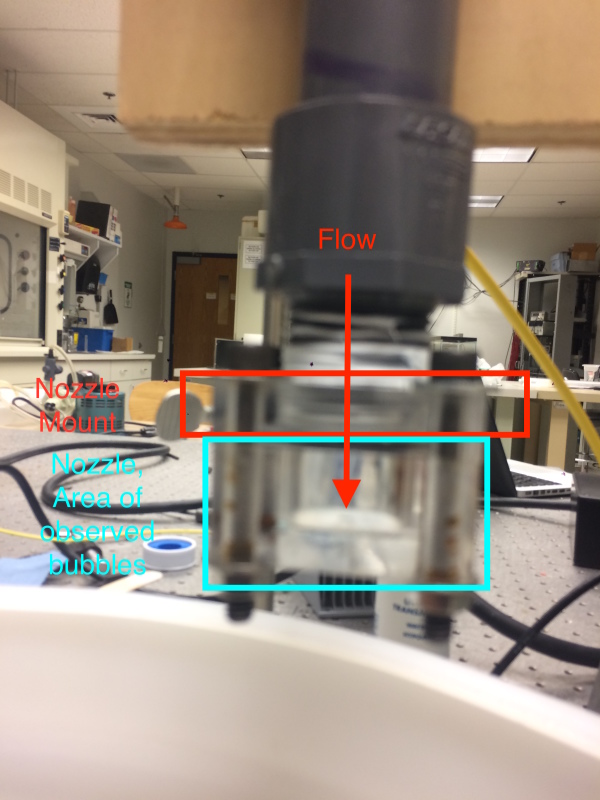
At 8 liters per minute(lpm), I am observing small bubbles around the PVC adapter and acrylic nozzle connection. Then as I increase the flow rate up to approximately 9 lpm a large bubble (approximately 1") forms.

My initial guess is that I have air leak in the nozzle mount and nozzle area. I placed an o-ring in between the nozzle and the nozzle mount but the issue still persist.

I apologize for such a long post. I tried to be as descriptive as possible. Please let me know if I need to clarify anything.
 
Replies continue below

Recommended for you

The joints are leaking. Use of a hose which is more flexible as well as a sealant may help. Talk to your hardware supplier.
 
Nice pictures, but I still can't tell where the nozzle, o-ring, nozzle mount, meter and PVC adapter are. A simple sketch with a couple of notes and arrows would be just fine.

Why do you need such a tall upwards pipe run and the drop back down into the bucket?
How is flow going into the bucket controlled?
 
Agree with BI - please just sketch out the system and list the items you mention.

Pictures are good, but the top picture is very blurred. I'm taking a guess that the top picture is a close up of the end nozzle?

The fact you're able to see the bubbles implies it is in the see through plastic section at the high point where it joins the plastic section to the black (acrylic?) piping??

What sort of velocity does 8 and 9 l/min equate to in the tubing?
how warm is the water / liquid?

Options to investigate include:
air entrainment going into the nozzle from the tank (what submergence have you got?)
Possible cavitation / vapourisation of water entering pump / inside pump which isn't being absorbed when it's pumped out
Leakage of air into the system at the pump inlet (pressure less than atmospheric)
Insufficient velocity to push air out of the vertical piping
Inlet valve to pump partly closed
How do you vary flow?
where is the control valve?

It might sound a bit odd, but try lengthening the tubes and put the pump on the floor. Won't make any difference to the differential head as the head will balance out.

Or put some blocks under the tank and raise the tank compared to the pump

Remember - More details = better answers
Also: If you get a response it's polite to respond to it.
 
The system starts with a load of air above the tank.

Put a tee and a valve in place of the top elbow so you can bleed the air out of the hump for a few seconds after the pump starts.


Mike Halloran
Pembroke Pines, FL, USA
 
Is that air above the tank supposed to be a joke?

The problem is that the hose and barb do not match. The hose also needs to be softer and more pliable than the barb.

Consider buying better quality hose and fittings, from the same supplier/manufacturer.

Designers spend a lot of time choosing the right tubing or hose for an application yet sometimes the decision on fittings or couplings receives less scrutiny. In fact, a secure and reliable connection is really determined by how well the connector and tube work together. This makes selecting the right connector just as important as tubing choice.

A hose barb is one or more continuous ridges or bumps on a connector that grips the inside diameter of a tube and seals the connection. Installing a tube on the connector expands it over the barb. As the tube relaxes to its original diameter the barb grips and seals it. For many applications, one barb on a hose connector provides 100% of the sealing and most of the holding for a tube termination.

Slope and depth of the barb, sharpness of its gripping edge, number of barbs, and their spacing all contribute to how well the fitting grips and seals. The internal diameter of the tube, flexibility of its material, and the intended application all factor into the decision on which connector to choose for the job.

Rubber hoses and plastic tubing have different levels of flexibility, which play a large part in how well a connection performs. In general, the softer the tubing, the more likely a hose barb connector is appropriate for the application. While the inside diameter of the tube determines selection of the proper connector, consider other factors as well when selecting a barbed connector.

Pull-off resistance. Pulling a tube generally makes it contract and grab the barb tighter. When the barb is too sharp and the tubing is soft, enough pulling and vibration can cut the tube material and cause leaks. On the other hand, a shallow or rounded barb mated with stiff tubing may be too easy to pull off.

Blow-off resistance. Spikes in pressure can make tubes expand, potentially loosening their grip on the barb. For high-pressure applications, the shape and arrangement of barbs and the relative flexibility of the tubing determines how the connection will perform under expansion of the tubing material.

Ease of installation. Shape and placement of barbs on connectors combined with tube flexibility determine the force required to terminate (remove) a tube. More important, if it is too difficult to push a tube over the connector, the tube may not be installed correctly and may leak.

It is tempting to conclude that more barbs on a connector provide better holding and sealing power. This is not always true. Many things work together to determine the quality of the connection between a hose barb and tubing. The sharpness of the barb, parting lines, surface finish, and the barb angle contribute to the quality of the connection. Failing to optimize these aspects will result in a poor connection, regardless of the number of hose barbs used.

There are cases where the number of barbs is important and this is more a factor of the application than the specific number of hose barbs. For example, connectors for biopharmaceutical manufacturing or chest drains use extremely flexible, soft silicone tubing and may work best with a single hose-barb design. However, that same single barb will not work as well in an application using reinforced hose or a stiffer tubing in which the ID of the tubing does not sufficiently relax around the barbs. In this case, multiple well made barbs with sharp edges provide more holding force and a more secure connection.

While the hose barb effectively grips the inside of the tube, ties (or clamps) provide an extra measure of holding power from the outside. The decision to use ties depends on tubing material, system pressure, and environmental conditions. For tubes without memory, ties or clamps are often necessary. Tubing that has been repeatedly installed and removed over one or more barbs and is no longer elastic enough to relax behind a barb will also require a tie. When pressures and temperatures are unknown, or vibration is an issue, ties are an important element for connecting tubes to connectors.

On the other hand, with higher quality materials such as braided tubing, or in a range of pressure systems, ties may not be necessary. In these cases, the hose barb provides more than enough blow-off and pull-off resistance.

There is a downside to ties. If installed incorrectly, ties can actually induce leaks. When a tie-type clamp is cinched too tightly on a soft tube, it can lift the tube away from the connector and open a leak path. Securing a tie over the portion of tubing that is stretched directly over a barb can degrade the seal enough to cause leaks or reduce pressure.

 
How does and where does the water originate for the supply tank?
Possible you are supplying the pump with aerated water.

It is a capital mistake to theorise before one has data. Insensibly one begins to twist facts to suit theories, instead of theories to suit facts. (Sherlock Holmes - A Scandal in Bohemia.)
 
The gate valve stem seal lets air enter the suction line.

The flow rate may not be sufficiemt to fill the down leg to the bucket.

Ted
 
The valve on the tank, can you put it on the inside so it is submerged, then just run the tube on the outside?
 
Thank you for all the feed back.

I have included a diagram of the system (the flow is designated with the blue line)(please ignore the other items).

experimentaldiagram_121316_hc3nbs.png


BigInch: The flowmeter required a specific length in/out of the meter. Although, I can rotate that pipe 90 degrees so everything is lower. I am suspicious of trap air at the top of the pipe and would hope this would solve the problem. The flow is controlled with a variable frequency driver on the pump.

LittleInch: Yes, the inspection point that I am referring to is the acrylic section of my nozzle setup. The nozzle is acrylic and it is connected to schedule 80 PVC (grey) adapter (NPT). The pipe is 1 inch and at 8-9 lpm then the velocity 0.263-296 m/s inside the pipe. Water is at room temperature.

Artisi: The water is regular tap water. I will also try degassing the water.
 
As noted in some of the other posts, basically once you get air inside, your velocity is insufficient to blow the air out of your nozzle.

Hence you either need to include a vent at the high point or have all of your tubing gently sloping upwards to the tank.

Or run it at a velocity of > 1m/sec at which point the system will flush all the air out.

Running a turbine meter with air around will give you some false readings.

If you replace the acrylic elbow with a tee and then put a valve on top this will allow you to vent out the water when under flowing conditions.

Lots of people make automatic vents for heating systems e.g.
Note that this only works if the pressure at the high point is greater than atmospheric pressure....

Remember - More details = better answers
Also: If you get a response it's polite to respond to it.
 
hydtools: can you elaborate on your points?

I am convinced that I am getting air trapped into the system. I believe a big source is through the test section. When I turn off the pump the nozzle begins to suck air into the line. What are some good practices or add ons that I can use to prevent air from sucking into the line when I turn off the pump.
 
hydtools stated you may have air leakage on the gate valve stem seal that lets air enter the suction line.

However, it appears you have a PVC ball valve, which is probably less susceptible to leakage.

In addition, the pipe that flows downward to the return tank will have a siphon effect on the system. This pipe may not be flowing full at lower velocities.


What exactly are you trying to do with this setup? If the purpose of the setup was known, it would make it easier to address the problems that you are having.

Why do you have a return tank, instead of returning to the supply tank?
 
The purpose of this setup is to drive flow into a nozzle/orifice to cause cavitation. I specifically wanted to keep the supply and return tank separate to minimized the bubbles entering the line.

At the moment, when I run the flow circuit, I can already see large bubbles entering the orifice via a "window" . These bubbles are persistent (and annoying). As I drive the flow relatively higher (2gpm max) they are there. I am convinced I have an air pocket inside my line somewhere. As I drive the flow up, small pockets break off and that is what I am seeing. I can run the set up for a while and the bubbles are still there which leads me to believe I probably have a leak. Also when I turn off the setup the siphon effect definitely introduce more air into the line.

At the end of the day I just want flow controlled cavitation. The simpler the better! Any suggestions would be much appreciated.
 
xhuydo,

If you read the posts above we've all told you what you need to do and where your issues are.

Re-reading this you don't appear to have enough velocity / flow rate in the tubing to drive out the air which is present, but the air bubble there lets a small amount go every now and then as the water flows past it.

Therefore you either:
1) Need to temporarily increase the flow rate, possibly via a tee before your nozzle to clear all the air out
2) slope all the tubing in one direction and then add a tee with a vent valve to remove the air.
3) Add a non return valve on the discharge of your pump to prevent back flow

Note that due to the vertical piece of pipe, you might get air in the vertical tube when you stop as it drips or flow out under gravity. I'm not sure you will ever be able to fully get that vertical leg air free unless you're flowing at more than 1m/sec.

Would your experiment work just as well if the pipe was horizontal?

Can't you use a tap and the mains supply?

Remember - More details = better answers
Also: If you get a response it's polite to respond to it.
 
Install a larger pump to ensure you have velocity to push the bubbles downstream. That would be a velocity of 5-6 ft/sec.

Install a return loop that would begin just prior to the nozzle/orifice and transfer the excess flow back to the supply tank.
 
xhuydo said:
I can run the set up for a while and the bubbles are still there which leads me to believe I probably have a leak. Also when I turn off the setup the siphon effect definitely introduce more air into the line.

Could you plug one end and run a low-pressure-air leak test using some soapy water and a brush?
The leak should be along the low pressure section, including the pump.

I may be wrong, but it seems to me that the meter and nozzle do not need to be vertical.
A long radius elbow or hose downstream the nozzle or discharging into the bottom of another tank (or same tank with some internal baffles) could solve the problems associated to the inverted P-trap.

"God will not look you over for medals, degrees or diplomas, but for scars." - Elbert Hubbard
 
I agree with littleinch, run your setup horizontal.

Ted
 
I ran the system horizontal and it worked like a charm. Thank you for all the suggestions!
 
Status
Not open for further replies.

Part and Inventory Search

Sponsor