Eng-Tips is the largest engineering community on the Internet

Intelligent Work Forums for Engineering Professionals

Uplift due to gravity loading in reinforced concrete structures 2

Status
Not open for further replies.

Gus14

Civil/Environmental
Mar 21, 2020
184
0
0
KW
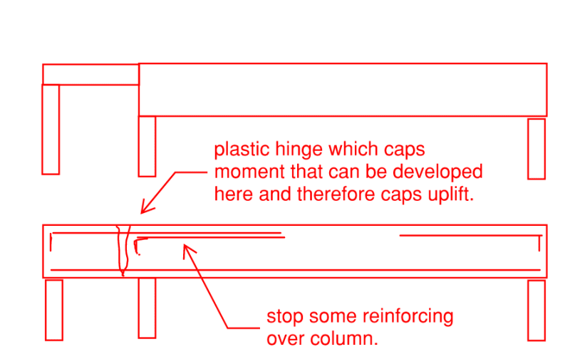
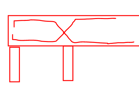
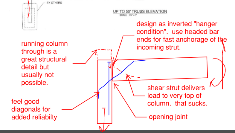
In reinforced concrete continuous beams with unequal spans similar to the attached sketch. Under gravity loading Column (A) has an uplift reaction. How would you detail the beam to column joint to transfer this uplift force ?

Also since this uplift force causes an increase in the reaction at column (B) are there ways to go around it ? There are two options I can think of but I am not really convinced with them :

1. Assume that each span behaves as a simple beam ( allow for more than 30 percent moment redistribution ).

2. Assume that the short span will work as a cantilever and design for it.


 https://files.engineering.com/getfile.aspx?folder=4a698128-a3bb-4885-956f-8edd14777b85&file=Sketch.pdf
Replies continue below

Recommended for you

1. No - They aren't simple spans and won't behave that way.
2. No - Also it's not a cantilever and won't act that way.

The uplift is simply a reverse shear force on the column/beam interface area.
The uplift ends up as a tension force in the column so you need to ensure that the column longitudinal bars are hooked at the top.
I'd also ensure that my beam bars (top and bottom) are hooked into the column and developed past the column face.


I sometimes have similar problems when designing structures. [upsidedown]

When I get into trouble with gravitational loads I find one of the easier assumptions is to assume gravity isn't present. That does give me some issues often with resisting wind so then I assume that my structure is in a vacuum. (this also makes most of my live loads into dead loads) Seismic loads often become problematic but if I assume the interface between my structure and the surface is frictionless then I can do away with those issues too.

The design all works out very nicely. Though for some reasons my colleagues keep telling me that I should be a physics teacher and not an engineer.
 
The column bases are presumably modeled as rigidly restrained in the vertical direction. Depending on the type of foundation system, they probably aren't. If you have a subgrade modulus, you might try to figure out the stiffness of a vertical spring at the bottom of each column. That might reduce the uplift on Column A.
 
Thank you everyone for replying.

JAE said:
1. No - They aren't simple spans and won't behave that way.

I think it's not a good detail, but withstanding the explicit code requirements, I have seen some plans where the beams were assumed and designed to act as simple beams. This is done by designing each span as simply supported and provide one third the bottom reinforcement over the columns. The top reinforcement would end in the column and not extend into the adjacent span. Theoretically, this would prevent uplift at the expense of some level of concrete cracking near the columns, an increase in the long span bottom reinforcement and deflection and a decrease in the building overall structural integrity.

With taking uplift into consideration, as an additional study case I would study the beam as a cantilever that would prevent local failure in the columns/joint with uplift from undermining the building safety.

human909 said:
The design all works out very nicely. Though for some reasons my colleagues keep telling me that I should be a physics teacher and not an engineer.
I did consider becoming a physics teacher at some point [bigsmile].

271828 said:
The column bases are presumably modeled as rigidly restrained in the vertical direction. Depending on the type of foundation system, they probably aren't.

Interesting approach, but usually the footing self weight and back fill weight are enough to prevent the uplift.
 
That would only prevent uplift on the soil. The columns would still have full uplift load.

--Einstein gave the same test to students every year. When asked why he would do something like that, "Because the answers had changed."
 
Yeah prevent the footing from going up. The column still needs to be designed for uplift force. Mechanical splices should be used too.
 
Gus14 said:
Interesting approach, but usually the footing self weight and back fill weight are enough to prevent the uplift.

I was trying to say something else.

Consider a continuous beam with two spans (each span L long) and pin and roller supports that are rigid vertically (a coarse idealization in some cases), constant EI, and uniform load (w). Typical linearly elastic analysis. The reaction at each end is 0.375wL and the reaction at the interior support is 1.25wL.

If you replace those pins and rollers with vertical springs, the reactions might change quite a bit. This is a more realistic analysis in some cases.

That might be true for your beam. There might not be much or any uplift at the left support.
 
human909 said:
When I get into trouble with gravitational loads I find one of the easier assumptions is to assume gravity isn't present. That does give me some issues often with resisting wind so then I assume that my structure is in a vacuum.... I should be a physics teacher

I take a computer science approach, I assume that IF wind is acting THEN gravity is present, ELSE gravity = 0. That way you can count gravity where you need it, but ignore it for pesky things like column uplift.

Another way to eliminate column uplift is to take "tributary area" approach. PROBLEM SOLVED.
 
Gus14 said:
I think it's not a good detail, but withstanding the explicit code requirements, I have seen some plans where the beams were assumed and designed to act as simple beams. This is done by designing each span as simply supported and provide one third the bottom reinforcement over the columns. The top reinforcement would end in the column and not extend into the adjacent span. Theoretically, this would prevent uplift at the expense of some level of concrete cracking near the columns, an increase in the long span bottom reinforcement and deflection and a decrease in the building overall structural integrity.

Something similar to what you've described is what I normally see done. One of two approaches:

1) Reduce the depth of the short beam such that it's lowered stiffness mitigates the uplift generated at the leftmost column. This can be unpopular as contractors often want to carry the same formwork across both beam spans. One option for addressing that is to carry the same formwork through but then block out the bottom of the beam form to get your reduced beam depth.

2) Design the reinforcement at the joint between the two beams such that it generates a plastic hinge which caps the magnitude of the uplift reaction. This requires one to design both beams for something less than full beam continuity across the joint. Maybe that's a simple span design, maybe it's something else. Designer's choice. One doesn't want the strain in the rebar that passes through the hinge to rupture the bars but, for fairly stiff beams, that ought not be an insurmountable problem

c01_yplmsd.png
 
You'll also see folks attempt these flexural hinge setups. This isn't my preferred approach as it's complex and you'll need some crack control bars at the top anyhow.

c01_bz3uii.png
 
I would do it as shown below. Frankly, without the stub up, it's not a joint that I would have a great deal of confidence in.

OP said:
How would you detail the beam to column joint to transfer this uplift force ?
c01_mph57s.png
 
Thank you Kootk for replying.

Both great approaches. With the first one I can reduce uplift by (40-50) percent without having to assume gravity is not present [bigsmile]. I just need to pay attention that the smaller section is not over reinforced.

Also, I think applying the first approach with the 30 percent moment redistribution limit allowed by the code will reduce uplift even further, but I am yet to see a document showing the moment redistribution effect on columns reaction.

Kootk said:
This isn't my preferred approach as it's complex and you'll need some crack control bars at the top anyhow.
I agree.

Thank you for sharing the joint detail.
 
Status
Not open for further replies.
Back
Top