Continue to Site

Eng-Tips is the largest engineering community on the Internet

Intelligent Work Forums for Engineering Professionals

  • Congratulations KootK on being selected by the Eng-Tips community for having the most helpful posts in the forums last week. Way to Go!

Upon reusing an older calculation, 3

Status
Not open for further replies.

FL_Sem

Structural
May 8, 2018
29
Upon reusing an older calculation, we noticed that the rebar provided for concrete breakout in a Seismic Design Category D region, is insufficient in quantity. The foundation has already been poured. Are there any mitigation techniques that don't involve tearing up the concrete?

Also, when designing anchor bolts for overstrength load combinations, does the ductility requirement still apply?

Thanks!
 
Replies continue below

Recommended for you

SuKaly said:
@KootK the concrete is well over 100% utilization for said load. Anchorage is just fine. So this is going to not be an easy fix, sounds like!

Don't be coy, how much over? The only other non-invasive trick I can think of is to base your numbers on 56 day concrete strength and back that up with some cylinder testing. It's slow going making up the difference though as the improvement climbs with SQRT(f'c). If you only need 15% or so, you might get there.


I like to debate structural engineering theory -- a lot. If I challenge you on something, know that I'm doing so because I respect your opinion enough to either change it or adopt it.
 
@CANPRO Thanks! This was my initial thought, without adding any more bolts/base plate etc.
 
Do cores of the in situ structure if you are going to think about actual in situ strength. Cylinders will give you are feel for it, but nothing like testing the actual placed concrete when you are trying to sharpen your pencil.

Can you hydro-demolish a squareish hole to the base and then install a plinth that the bolts lap with and which the plinth reinforcement by virtue of having a bigger footprint than your bolt group essentially increasing the breakout surface. Size plinth and detail plinth size to give you the required strength (drill bars in sideways to the original concrete to achieve a good construction joint. Basically you don't need to demolish the entire thing if it can be helped.
 
What is this connected to? Where does the 500 kips go - assuming that you have a mechanism to get it out of the bolts?
 
It is a transmission tower anchor bolt design.
 
Have you thought about my "embedded column" idea above? I'm not sure what the ties are....but if they are good....you aren't talking Appendix D anymore. You are talking ripping out by the punching shear equation.

 
Yeah, short of having a some kind of Hogwarts, exponentially increasing strength gain curve, you're probably in for a rough ride here.

350% over-stress basally means that you'd need an underside anchor plate the size of a small swimming pool to get this done. The lines blur but, at this point, I'd call this a failure of footing design rather than an anchorage connection failure.

Transmission towers aren't my wheelhouse but is there any way that one could claim energy dissipation via foundation rocking and just try to prove that your anchorage could lift the footing clean off of the ground. It a good enough story for a lot of high-rise buildings apparently.

I like to debate structural engineering theory -- a lot. If I challenge you on something, know that I'm doing so because I respect your opinion enough to either change it or adopt it.
 
@KootK yeah, transmission towers are new for me too. Interesting idea on the energy dissipation. I'll do some research. The foundation is actually drilled piers with a 4' pile cap, but unfortunately no piers right under the bolt locations. Seems to me like the failure will be local "ripping off" than whole foundation lifting up.

 
@WARose, I'll start researching that idea.
 
@WARose, I'll start researching that idea.

You aren't going to find it anywhere (that I know of). It's a combination of ideas. You get the vertical load from the bolts to the "column" by bearing, then you are in it. After that (assuming you've got the verticals properly tied and the geometry makes sense), it's then a matter of the "column" ripping out by a 2-way shear failure in concrete (depending on where it is relative to the edge).

It's just like a column bearing.....but reverse. I've used it a few times.....and no phone calls yet.
 
How far along is the construction for this, just foundation and anchor bolts?
 
WARose said:
Have you thought about my "embedded column" idea above? I'm not sure what the ties are....but if they are good....you aren't talking Appendix D anymore. You are talking ripping out by the punching shear equation.

I respectfully object to this strategy:

1) Punching shear is not designed to apply to columns in tension.

2) I see it as irrational to expect this mechanism to somehow be better than a hypothetical rigid anchorage plate plowing through the concrete from the lowest point of anchorage.

3) Mathematically, the app D and punching shear numbers for this appear to be almost identical with the app D numbers coming in just the slightest bit lower.

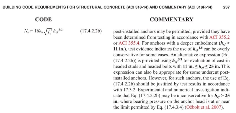
4) ACI commentary on the App D numbers indicate that even they might be unconservative for anchorages deeper than 25 in.

WARose said:
It's just like a column bearing.....but reverse.

I think that's in error in a very important way. A column in bearing delivers shear via compression struts originating on the far side of the concrete. That's about as good as things can get. A column in tension delivers shear as compression struts originating from the bond stresses transmitted throughout the interior of the concrete. And the bits emanating from the hook elbows. That's considerably less good.

c01_nvo3e4.jpg


I like to debate structural engineering theory -- a lot. If I challenge you on something, know that I'm doing so because I respect your opinion enough to either change it or adopt it.
 
I don't really buy the anchor bolts bearings into the column analogy. You still need to get that tension to the bars and then the bars can break out like a column. When you bear on top of an actual column, it's compressive force (as a fanned strut) that spreads through the column and applies a pressure over the base. Here, the anchor head bears on concrete, and the fanned strut has no concrete to bear on. You'd have to intercept the strut with rebar and develop that into the column section, and now it turns out it looks a whole lot like intercepting the failure cone from concrete breakout.

Edit - of course koot beat me to it by a few minutes...

Being more productive, the only way out I see other than tearing the concrete up is adding more concrete (ie mass) until your uplift can be resisted by what you've got there.
 
Is the seismic load on your transmission tower really that high? I've found seismic to be a small fraction of the loads typically seen from the wind/ice on the conductors.
 
What about coring a large diameter hole at the location right through the slab and installing another pile and put the HD bolts directly into the pile. New pile replaces the pad, do it at all support locations to avoid any settlement issues. i.e. do what you do on every other site?

There should have been some shear ties (and suitable longitudinal reinforcement) in the slab thickness to pickup this load and transfer it to the piles you just mentioned.

One other option worth considering might be to use those double headed studs they use for enhancing the punching shear capacity of thinner slabs, but use longer ones and grout into cored holes. Those have the advantage over plain straight bars as having much better/shorter anchorage lengths which is what you need here. Although I suspect by the time you are finished you have turned your slab into swiss cheese with 1001 holes.

All this shagging around and you might find its better to wholesale demo part of the slab and do it right.

One point people have not/semi mentioned yet, is the loadpath to the piles and this interface transferring a similar load in tension depending on the exact arrangement. I suspect this part won't work either given the 350% stress issue for the bolts and if its simply the reverse of what you have here for the piles, albeit with a larger outline of the pile and pile hooked bars to the top of your slab.

I think when you are 350% of the design actions, a bandaid is not going to stick too well, you need to put your hand up and redesign it so it works and probably demolish the entire thing and start again.
 
[blue](Kootk)[/blue]

1) Punching shear is not designed to apply to columns in tension.

And this isn't a column in tension. Inside of the punching shear perimeter (above the bearing), it should be in compression.


[blue](Kootk)[/blue]

3) Mathematically, the app D and punching shear numbers for this appear to be almost identical with the app D numbers coming in just the slightest bit lower.

If that is correct, it may not be worth it. But where the "d" (i.e. for the punching shear) starts for that is a bit tricky.

 
WARose said:
And this isn't a column in tension. Inside of the punching shear perimeter (above the bearing), it should be in compression.

It's a "tension" column in the sense that it's a force pulling away from the concrete rather than punching into it. In my estimation, that's kinda the thing here.

WARose said:
f that is correct, it may not be worth it. But where the "d" (i.e. for the punching shear) starts for that is a bit tricky.

Well, they're only close to equal if one accepts that punching shear is an appropriate way to look at this. I'm arguing that it's not.

Another thing that bothers me about punching shear here is that you wouldn't have the concentrated flexural steel at the column that UofM research has indicated is so important for punching shear to do its thing. I know the counter argument though: "but we do punching shear on footings all the time and rarely concentrate the bottom steel under the columns!". Yup, hate that too.

I like to debate structural engineering theory -- a lot. If I challenge you on something, know that I'm doing so because I respect your opinion enough to either change it or adopt it.
 
[blue](Kootk)[/blue]

It's a "tension" column in the sense that it's a force pulling away from the concrete rather than punching into it. In my estimation, that's kinda the thing here.

It's creating a confined chunk of concrete that has to be ripped out. It's certainly better than a embedded plate (which is outside the scope of Appendix D as well the last time I looked) that gets used all the time.

[blue](Kootk)[/blue]

Another thing that bothers me about punching shear here is that you wouldn't have the concentrated flexural steel at the column that UofM research has indicated is so important for punching shear to do its thing. I know the counter argument though: "but we do punching shear on footings all the time and rarely concentrate the bottom steel under the columns!". Yup, hate that too.

I would expect a flexural check with this....so I'm with you on that.


Status
Not open for further replies.

Part and Inventory Search

Sponsor