Eng-Tips is the largest engineering community on the Internet

Intelligent Work Forums for Engineering Professionals

USB 2.0 Strange Signal Issue

Status
Not open for further replies.

Kepco

Electrical
Jun 1, 2011
27
0
0
US
Hi,
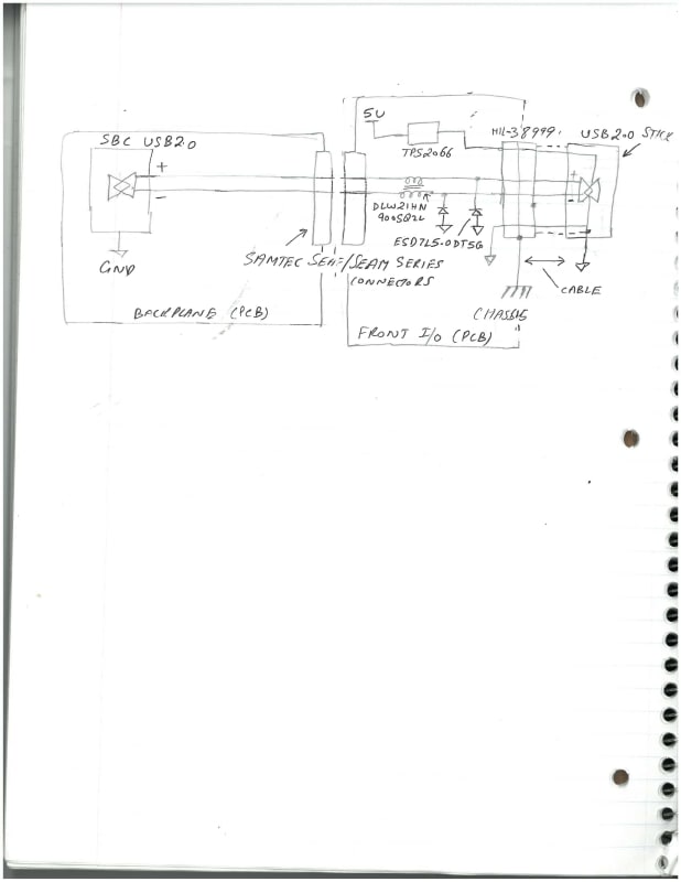
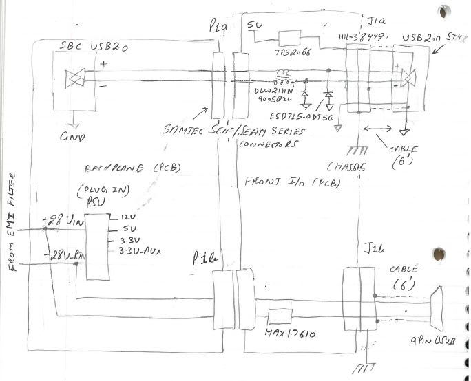
We are working with a USB2.0 design that has attached circuit block diagram. The USB2.0 is working intermittently. USB 1.0 works fine. We have ruled out a few things now. We are doing eye pattern under various scenarios and trying to see what is causing the issue. We are reading eye pattern on USB 2.0 drive connector pins. Our observations are following so far.

1. Choke DLW in schematic has no negative impact on eye pattern. We shorted the choke with no change to the signal.
2. Diode ESD has no negative impact on eye pattern. We removed the diode with not change to the signal.
3. There is no noticeable negative attenuation from SEAF/SEAM connectors or at MIL-DTL-38999 connectors.
4. The PCB routing is fairly straight forward with correct impedance of 90 ohms.
5. USB voltage is 4.9V and is within specification.
6. Rise and fall and voltage are within USB specification.

What we know so far is that if shell of MIL-38999 connector is connected to chassis plane on the Front IO PCB we get a bad eye pattern. If this connection is left floating then we get good eye pattern. The scope shots of signals and eye pattern are attached with shell connected to chassis plane and shell not connected to chassis plane. Interesting thing is if the chassis plane is left unconnected to chassis we still get same behavior and signal comes out bad. We are not connecting Chassis to Digital GND in our design but USB2.0 stick connects shell to the Digital GND that connects chassis to Digital GND when mated with cable.

The USB 2.0 Signal is generated by putting USB2.0 host in test mode using USB.org provided test software called USBHSETT. This tool takes over the USB 2.0 driver and put the host in test mode where it can send packets so that eye pattern can be obtained. The scope is 24GHz Tektronix scope.

Any thoughts on the issue will be much appreciated.

Thanks
 
 https://files.engineering.com/getfile.aspx?folder=dfe41663-9d78-4cf4-9188-ac49dc77e723&file=USB_2.0_Circuit.zip
Replies continue below

Recommended for you

Note: I can't open your zip file at this time.

If you haven't already, check for voltage differences between the various 'grounds' and check for resultant currents.

Then think about shielding, and keeping induced common mode current off your signal lines.

 
Grounding in certain electrical designs is not for the faint of heart; some grounds are not true grounds. Note that differential circuits are never ideal, since the circuits that implement the functions have limitations on common-mode voltage, and floating grounds are often recipes for disaster.


Zip file contains bunch of scope images and schematic below
USB_2.0_Circuit_Block_Diagram_jlbn8l.jpg


TTFN (ta ta for now)
I can do absolutely anything. I'm an expert! faq731-376 forum1529 Entire Forum list
 
Just in case it's not grounding issues...

How long is the cable (shown on the right side)?

Are there other power or signal wires contained in the same cable?

And is the USB wiring correctly twisted-pair and appropriately shielded?

Is the twisted pair dressed and twisted neatly right up to the 38999 pins?

Are the 38999 pins chosen with Z in mind?

A single overall impedance number won't necessarily show an impedance bump from bad wiring at the connector. Might need a TDR to see it, or just look at it (eyes) to make sure it's done as neatly and Constant-Z as possible.

For comparison: Gb Ethernet (at 250 Mbps each pair) has become quite common via 38999 type connectors, but it involves being careful at the connector. I believe that USB is a more 'delicate' signal.

---

Also worth mentioning, don't get too focused on the Eye Pattern. Make sure to check the more obvious things, such as looking for AC power line noise. In other words, ensure it's not simply a big-simple problem before worrying about the details.

Poke around with a DVOM, including in AC mA series mode if feasible. Poke around with an oscilloscope with Time Base adjusted to display AC power frequencies, or Switching frequency if there's a SMPS involved.

Inspect things, because it's not uncommon that the issue is a build error, not visible on the design drawings.


Thanks VEIBLL and IRstuff.

You guys are certainly correct on the point that this a grounding issue. But let me first answer the questions.


How long is the cable (shown on the right side)?
(K) The cable is 6 feet long.

Are there other power or signal wires contained in the same cable?
(K) Yes, there are signals and power. I have updated the circuit drawing to show power wires that are affecting the USB 2.0 working.More on it in the end.

And is the USB wiring correctly twisted-pair and appropriately shielded?
(K) Yes. We are using original USB cable and cutting one end and crimping the cut end and inserting it in 38999 connector.

Is the twisted pair dressed and twisted neatly right up to the 38999 pins?
(K) The twisted pairs are dressed as practical as possible close to the connector. May be for about half an inch they go straight in connector.

Are the 38999 pins chosen with Z in mind?
(K) Not really. We are using standard size 22D PC tail contact. We have used this in lot our designs with no issues in the past.

A single overall impedance number won't necessarily show an impedance bump from bad wiring at the connector. Might need a TDR to see it, or just look at it (eyes) to make sure it's done as neatly and Constant-Z as possible.
(K) When the USB 2.0 works the eye pattern is very solid. So effects of any impedance related issues are not obvious at this point.

For comparison: Gbe Ethernet (at 250 Mbps each pair) has become quite common via 38999 type connectors, but it involves being careful at the connector. I believe that USB is a more 'delicate' signal.
(K) We also have 1 Gbe Ethernet on this connector and it works with no problem. We have lot of complex I/O on these connectors with multiple serial protocols, Ethernet, USB2.0 etc with no issue in one connector in the past. But this one acting quite odd.

Also worth mentioning, don't get too focused on the Eye Pattern. Make sure to check the more obvious things, such as looking for AC power line noise. In other words, ensure it's not simply a big-simple problem before worrying about the details.
(K) I agree with your statement. This seems like a big simple problem. Our system is 28V system. It takes in 28V as main input power. I noticed noise on USB2.0 diff pair + side with reference to digital GND and same thing on diff pair - side with reference to Digital GND. But cannot put finger where this is originating.

Since yesterday we did some more testing and have some more findings.

Refer to the updated circuit below in that regard. P1a and P1b are sub parts of same connector. J1a and J1b are sub parts of same connector.

USB_2._Circuit_3_pv6j4w.jpg


What we are noticing is if we disconnect the shield of 28V and 28V RTN twisted pair wire from the 38999 connector shell side the USB2.0 works and reconnecting it makes it intermittent again and it is repeatable. The 9 pin DSUB does not have any other signals on it and it is not powering anything. So the 28V power wire shield is contributing to the issue it seems. I am finding this behavior little weird at this point. Hopefully you guys have some insight into it.

Thanks again.
 
It is a technique * to ground the shields at only one end, assuming that you have dedicated power and signal return lines, as well as a wire to interconnect the two local grounds. Shields aren't supposed to carry (ground) currents between two boxes.

* I'm not sure how widely 'accepted' it is; as ideally the shields are 360° grounded at each end.

You should probably track down where the ground currents are arising, and confirm the theory at the same time. Use the frequency domain to provide clues (e.g. 60 Hz?). Turn things off, provide local battery power instead of supplying power, eliminate things one by one.

Also, beware in case it's just a bad part.

--

In previous projects with lengthy Gb Ethernet custom cabling, we been lucky to have an E3 Subject Matter Expert (SME) on staff that told us exactly how he wanted the 38999 connectors wired and assembled, down to the smallest detail: like dressing of the twisted pairs, selection of 38999 pins the optimum distance apart for Z, grounding, multiple shielding, etc. So we just followed the guidance and had zero issues. Even when swimming in a sea of EM interference.

 
> How is the ±28V being generated, and what is the 28VRTN coming from?
> Chassis connections in the old days used to be tied to neutral, which isn't actually a ground
> I would go with VEIBLL's suggestion and measure the current between the 28V shield and your shield
> Note that shields that aren't properly grounded have a nasty habit of getting AC-coupled to line, often resulting in excessive voltage and ground currents that can cause noise problems
> Note that chassis ground IS NOT, and CANNOT, be circuit ground; any return currents running around in your chassis system is another noise source

TTFN (ta ta for now)
I can do absolutely anything. I'm an expert! faq731-376 forum1529 Entire Forum list
 
Yep. We've had schematics with three or four separate ground symbols. Analog ground, Digital ground, Chassis Safety ground, etc. In addition to explicit power and signal returns.

Area of the loop, between source and return wiring, should be minimized.

---

But Step 1 is make it visible.

"If electricity (RF, noise) was purple" (old joke), you could see the issue in seconds. But it's not purple, not visible, So measure measure measure. Make it visible. Don't work blind.

Find out what it is and where it's from.

Frequency domain is a great marker.


Hopefully you've debugged this by now. If not...

It looks like 28V RTN (or 28V) is inadvertently getting connected to the shield around the DB9 circuitry. This could be passing the 'chassis ground' noise onto your other return/ground nets and causing havoc. This could be as simple as a single strand from a poorly crimped wire touching the DB9 case.

Z
 
Status
Not open for further replies.
Back
Top