Continue to Site

Eng-Tips is the largest engineering community on the Internet

Intelligent Work Forums for Engineering Professionals

  • Congratulations KootK on being selected by the Eng-Tips community for having the most helpful posts in the forums last week. Way to Go!

Use of column curve (steel vs concrete design)

Status
Not open for further replies.

montbIanc

Civil/Environmental
Mar 11, 2023
21
Hi all,
I'm trying to understand the difference between steel and concrete design for buckling, specifically the 'column curve' for steel when applied to unbraced frames. Here's how I understand the two design processes:

1) Both steel and concrete design use lateral loads to simulate the construction tolerances - the frames aren't perfectly vertical.

2) Both steel and concrete use reduced stiffnesses in the analysis to account for the respective departures from perfect elasticity of nominal cross-sections. For steel, the reduction accounts for premature yielding due to residual stressed. In concrete, the reduction accounts for cracking and creep.

3) Both steel and concrete use second-order analysis to account for P-Delta effects (capital Delta).

4) Both steel and concrete use second-order analysis (subdivided analysis members) or moment magnification to account for P-delta (lower-case delta).

5a) For concrete, the columns not being perfectly straight between levels is accounted for by using a minimum (first order) bending moment that has to have moment magnification applied. For an unbraced frame subject to lateral loads, this usually doesn't govern so the axial force (P_ULS) and bending moment (M_ULS)from Steps (3) and (4) are checked against the cross-section interaction diagram. For the case of an unbraced frame under lateral loading, Step (3) usually governs (i.e. the end moments rather than the mid-height moment).

5b) For steel, the columns not being perfectly straight between levels is accounted for by the column curve which reduces the axial capacity compared to the pure cross-section capacity.

So, in effect, there's an extra step in steel design for the lateral load case(s) in unbraced frames. What's not clear to me is whether that's just extra conservatism or whether concrete design misses something.

I understand how the column curve comes into the design of columns in braced frames because they have small bending moments so the P-delta (lower case) effect at the column mid-height due to the column not being straight is significant, but the concrete method makes more sense to me for unbraced frames where the mid-height moment is small and the additional moment due to non-straight initial shape will not make mid-height moment larger than at the ends.

I'm thinking that the column curve applied to unbraced frames is a hangover from the days when the effective length was used instead of lateral loads in Step (1) because the end moments were underestimated by the analysis due to no allowance for the frame to be non-vertical as opposed to the current use for non-straight.

Agree/disagree?
 
Replies continue below

Recommended for you

I'm pretty sure I'm not following you fully.

Steel columns account for initial imperfection (sweep), rolling variations in thickness, residual stress, and (probably) out of plumb in the column design provisions. They tend to be "outside" the lengths where P[sub]y[/sub]A[sub]g[/sub] would work fairly accurately. AISC spec limits primary compression elements to kl/r of 200 (or whatever equivalent for k is going around these days). They are either I shaped or hollow boxes, typically.

Concrete columns tend to be a lot more stout, i.e. preventing buckling is kind of an implicit objective. Reinforcement ratios are controlled at least partly by the constraints of normal concrete placement (i.e. the 4% limit), rather than going anywhere near some kind of "optimal" rebar and concrete mix, and I'd expect it's fairly uncommon for a concrete column to develop tension along the length of the column. They are also typically solid.

So the two don't really mix.

They have design/analysis procedures that are appropriate to the typical range of sections/sizes/reinforcement and yield stresses (steel) they experience. For example, if you change the yield stress of steel, a lot of odd things like local buckling or cruciform buckling/torsional compression buckling can occur.

MontbIanc said:
I'm thinking that the column curve applied to unbraced frames is a hangover from the days when the effective length was used instead of lateral loads in Step (1)

You mean the axial compression capacity with the lambda and the 0.658 exponent? I wouldn't call that a hangover, per se, or a residual or a leftover, it came about around the same time, as the research "got there" and design and construction also drifted away from the "old way" with rivets and "everything braced" and A7 steel, but it's based on physical testing and there's reason to retain it. It's not like some appendix or gill slits or vestigial tail we no longer need or use whose purpose is no longer apparent. Residual stress is still there, variations in the cross section from rolling are still there, out of straightness is still there.

 
I also do not really follow, it is hard to understand what you mean.

The mechanics is the same, but the details are different.
Therefore, different methods were developed for the two materials to simplify the calculation procedure.

@lexpatrie regarding concrete - it's not always like that. Where I'm from most of the industrial buildings are made of precast concrete because it's the most economic option. Main lateral resisting systems are cantilever columns aprox. 10 m high (no bracing of any kind). Columns are usually kl/r = 100 to 120 and tension develops in them because they have low vertical and high horizontal load - buckling is almost always governing design.
 
Thanks for the replies. I don't blame you for the lack of understanding. I'm having trouble framing the question because I'm grappling to understand the issue. I'll try a picture.

Screenshot_sbfrtd.png


Before notional lateral loads, my understanding is that the unbraced effective length factor was used to account for the red portion of the moment curve "P-Delta [capital] due to not being initially vertical" (just the bit that's outside the orange). Because the non-verticality can be simulated with lateral notional loads, the shape of this P-Delta bending moment is the same as for actual lateral loads so adds to the maximum moments at the column ends. But now we use notional loads, so the column curve is instead used in steel design with the braced effective length factor to account only for the P-delta [lower case] moments. I've tried (crudely) to sketch those P-delta moments in blue. They don't add to the maximum moment at the column ends and generally have no effect on capacity for columns with significant reverse curvature, but the beam-column provisions always have a reduction due to this effect (use of Pc instead of Py). In summary, I think there should be something like the Cm factor from the B1 calculation to account for this since it's a very similar effect.

On the other hand, concrete design only accounts for initial non-straightness with a minimum moment. I guess that non-straightness is effectively ignored if the minimum doesn't govern, perhaps correctly (? - if my point about steel is correct) or perhaps with non-conservatism (presumably/hopefully only a small error).
 
OP said:
On the other hand, concrete design only accounts for initial non-straightness with a minimum moment.
Why do you think that? You're talking about small delta effect, right? This effect is considered in RC.
You can check this excellent short paper: It does not really matter what code you use, this should be very similar and the author of this paper proposed a great simplified method. I checked it agianst a more rigorous analysis and it gives good results.
 
I suppose I mean concrete columns outside the LFRS tend not to develop "excessive" tension...
 
Thanks hardbutmild. I didn't say it, but I was think about US concrete design. As far as I'm aware, the columns not being perfectly straight is only allowed for in the moment magnification procedure for the minimum moment. If the minimum moment is not applicable, there's no explicit consideration AFAIK.

However, I can see from the article you posted that the Eurocode design procedures do consider it, even in the simplest design method which the author said is still relatively complex. The simplified method from your linked paper matched quite well judging from the graphs and really is simple. I will test it out when the opportunity arises for comparison to the US code.
 
huh, I did not expect that.

I'm interested to hear if this method makes sense when using the US codes as well.
 
The internal effects on "stout" columns are less critical or influential, so it's possible the concrete version is taking that into consideration.

I don't think you'll find some grand unification that makes AISC and ACI align for columns, because they aren't dealing with the same material, for one, and the typical column effects are different due to inherent slenderness in steel design and inherent nonslender effects in reinforced concrete columns.

Keep digging though.
 
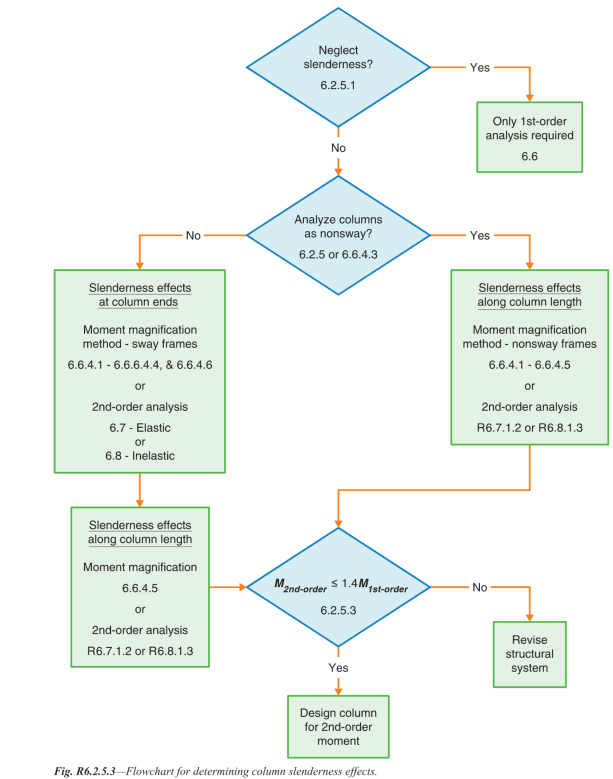
I looked up ACI 318 and I am kind of confused by your question. It DOES have a provision for both non-sway and sway elements. Look up 6.2.5, 6.6.4.5 and 6.6.4.6 (I'm using ACI 318M-19). Figure R6.2.5.3 is quite useful.
For non-sway elements only P-small delta is considered. This is done using a classic moment magnification method.
For sway elements additional magnification of end moments is done.

I do not understand what seems to be the problem.
 
montbIanc (Civil/Environmental) said:
1) Both steel and concrete design use lateral loads to simulate the construction tolerances - the frames aren't perfectly vertical.
Sort of.... In steel design we use notional loads to account initial imperfections, I don't know that for concrete but most software use pseudo lateral loads to account for that. P-delta is mainly to account for buckling not initial imperfections if that's what you are thinking.

montbIanc (Civil/Environmental) said:
2) Both steel and concrete use reduced stiffnesses in the analysis to account for the respective departures from perfect elasticity of nominal cross-sections. For steel, the reduction accounts for premature yielding due to residual stressed. In concrete, the reduction accounts for cracking and creep.
Yes, and it's somewhere under chapter 6 in ACI. Material stiffness reduces prior to buckling. The reduction is to account for those behaviors

second-order analysis is basically the fancy description of P-delta.

montbIanc (Civil/Environmental) said:
4) Both steel and concrete use second-order analysis (subdivided analysis members) or moment magnification to account for P-delta (lower-case delta).
Moment magnification factor is a simplified approach to account for buckling by penalizing your 1st order moments. Think of small P-delta as a finer mesh for your analysis. The finer mesh accounts for more points along a member giving more accurate results at a substantial computation cost depending on how big your building is.

montbIanc (Civil/Environmental) said:
5a) For concrete, the columns not being perfectly straight between levels is accounted for by using a minimum (first order) bending moment that has to have moment magnification applied. For an unbraced frame subject to lateral loads, this usually doesn't govern so the axial force (P_ULS) and bending moment (M_ULS)from Steps (3) and (4) are checked against the cross-section interaction diagram. For the case of an unbraced frame under lateral loading, Step (3) usually governs (i.e. the end moments rather than the mid-height moment).
Moment magnification is more of a buckling check, not to geometric linearity. If you have a slender column, you can either use the magnification factors or 2nd order analysis. It has nothing to do with braced or unbraced. Each is a method of analysis.

montbIanc (Civil/Environmental) said:
5b) For steel, the columns not being perfectly straight between levels is accounted for by the column curve which reduces the axial capacity compared to the pure cross-section capacity.
The curve is a member behavior, the stiffness is a material "behavior". There is a material stiffness reduction prior to buckling .


Typing on my phone. Took me so long to copy and paste and scroll. I will later check what I have typed up here.
 
it is easier to post than edit on the phone. For concrete refer to ACI 3108 chapter 6, for steel refer to chapter C (refer appendix for extra information). The Eurocode has something on initial imperfections, you might want to google on that. I think it's a great resource.
 
Thanks for the discussion.

lexpatrie said:
I don't think you'll find some grand unification that makes AISC and ACI align for columns, because they aren't dealing with the same material, for one, and the typical column effects are different due to inherent slenderness in steel design and inherent nonslender effects in reinforced concrete columns.
I don't think so either but am starting to think that being taught steel design, and concrete design, and timber design isn't the best way. The earliest subjects were structural engineering overall but looking back we hardly needed a researcher on the cutting edge of each material to teach us the very basics. Kind of like how the aluminum code was restructured to be in line with steel - make it easy to see how the requirements are all still addressing the same fundamentals.

And I don't really buy into steel usually being slender and concrete usually being nonslender or braced. The codes are meant to cover when those situations arise and the relevant provisions are simply not applicable most of the time.

hardbutmild said:
I looked up ACI 318 and I am kind of confused by your question. It DOES have a provision for both non-sway and sway elements. Look up 6.2.5, 6.6.4.5 and 6.6.4.6 (I'm using ACI 318M-19). Figure R6.2.5.3 is quite useful.
For non-sway elements only P-small delta is considered. This is done using a classic moment magnification method.
For sway elements additional magnification of end moments is done.

I do not understand what seems to be the problem.
My understanding is that these provisions are only covering the orange part of the bending moment diagram from my earlier sketch. The steel code actually has two additional requirements: 1) for initial overall lean of the structure (non-verticality) covered by the notional loads; and 2) initial non-straightness of individual columns covered by the column curve (possibly excessively covering this effect for sway frames as per OP). Both are real effects for concrete but not design requirements. (By the way, I was incorrect in the original post item #1 - the US concrete code doesn't require notional loads.)

BulbTheBuilder said:
Moment magnification is more of a buckling check, not to geometric linearity. If you have a slender column, you can either use the magnification factors or 2nd order analysis. It has nothing to do with braced or unbraced. Each is a method of analysis.
I take 'buckling' to be the combination of geometric and material non-linear effects that result in stability failure if pushed too far, so not able to be separated from 2nd order analysis. I agree those two methods you mentioned are different but basically equivalent analysis methods, but my question is relating to what is included/excluded from the analysis.
 
monbIanc said:
And I don't really buy into steel usually being slender and concrete usually being nonslender or braced. The codes are meant to cover when those situations arise and the relevant provisions are simply not applicable most of the time.

Uh, What? What "relevant provisions are simply not applicable most of the time"?

 
I meant that the concrete code should have comprehensive provisions for slender and unbraced columns even if most concrete columns aren't slender and/or are braced. As it stands, I believe that two real effects that may be significant in some circumstances aren't included (and one of them is over-included in steel). Because the commentary talks about what's in the code rather than what isn't, they don't say why those effects aren't covered.
 
Oh ok, now I understand.
I believe as lexpatrie mentioned, that it is not a part of the code because it is usually not that influential. It really depends what a code wants to be - american codes usually rely on the most common situation and that makes them great for everyday use. European codes tend to give you a more general aproach that is often less practical but covers more situations. Even the fib Model Code 2020 (a 700 page european style standard) only mentions imperfections briefly.
One thing that is also theoretically possible but no codes (that I know of) mention is lateral torsional buckling.
You are always allowed to consider more than the code requires. I guess you should find the tolerances in some sort of an american document (we have EN 13670) - maybe ASCE 7 has some guidance on the allowable imperfections.
Usually the maximal initial imperfection is about height / 400 (or height / 300 as usually the highest limit), but you can check the Eurocode. I doubt that there is a significant difference in the construction tolerances, but I might be wrong.
 
montbIanc (Civil/Environmental) said:
I take 'buckling' to be the combination of geometric and material non-linear effects that result in stability failure if pushed too far, so not able to be separated from 2nd order analysis. I agree those two methods you mentioned are different but basically equivalent analysis methods, but my question is relating to what is included/excluded from the analysis.

Yes, you are right with the buckling being a combination of geometric and non-linear effect.

For ACI 318-19, I'd refer you to
6.2.5 Slenderness effects
6.6.4 Slenderness effects, moment magnification method

For more literature on theory, European code has additional info on concrete.

Screenshot_2024-06-25_110010_ddxgrk.png
 
montbIanc said:
I meant that the concrete code should have comprehensive provisions for slender and unbraced columns even if most concrete columns aren't slender and/or are braced. As it stands, I believe that two real effects that may be significant in some circumstances aren't included (and one of them is over-included in steel). Because the commentary talks about what's in the code rather than what isn't, they don't say why those effects aren't covered.

If the cross section is not allowed, (excessive reinforcement, too slender) the code will not have provisions that address it. This starts to sound like Harbour Cay.

One does not traditionally design "slender" concrete columns. Hence my comment that the steel code and the reinforced concrete code are not trying to solve the same set of conditions in their provisions. That's what I mean by there being no "grand unification" where the two can be brought together and there's likely not a one-to-one set of approaches to the problems, because some of the problems will NOT occur. (i.e. local buckling for 80 ksi steel structural shapes), "crushing" of both materials will apply, to a degree, as A[sub]g[/sub]F[sub]y[/sub] is a hard upper bound on column strength in structural steel construction, but concrete "crush strength" is based on crushing of the concrete at a specific strain limit, not the "full" concrete strength, plus, confinement plays a role in concrete crushing strength (meaning the horizontal stirrups). One rarely has a column "hit" A[sub]g[/sub]F[sub]y[/sub] in steel design, I'm calling that "slender" with the quotations because there's a definition of slender in the AISC code that isn't what I'm talking about, I mean that the column generally does not achieve the "squash load" of A[sub]g[/sub]F[sub]y[/sub] (with appropriate safety factors applied).

These two design approaches are not trying to achieve the same goals, beyond the overarching "be safe", as the materials act differently.

Also, "pin-pin" concrete columns, while conservative, are a bit unrealistic on the safe side, as it is difficult to create a pin when the concrete is placed monolithically. Some of these provisions are analytically "incorrect" but produce reasonable designs that are safe (conservative). Going outside the provisions, that is potentially not the case, and going outside the provisions requires testing/research to establish the practice within the parameters of generally accepted principles of mechanics.

I can't decide if I'm being pedantic or if I'm actually contributing to the conversation.
 
Status
Not open for further replies.

Part and Inventory Search

Sponsor