Eng-Tips is the largest engineering community on the Internet

Intelligent Work Forums for Engineering Professionals

Use of voltage regulators with step-up transformer on distributed generation 1

Status
Not open for further replies.

rockman7892

Electrical
Apr 7, 2008
1,147
0
0
US

I'm looking at an application for a distributed generation wind site that currently has about 12MW of wind generation at 12kV that goes through collector system and step voltage regulator before interconnection point of 12.47kV utility distribution line (recloser and metering at interconnection point).

The distribution line is now being upgraded from 12.47kV to 25kV (24.9kV I believe). The existing voltage regulators are 667kVA units rated at 13.2kV so they will not provide the necessary boost required to 24.9kV. Initial approach is to add a new step-up transformer (aprox 15MVA) into collector system to bring 12kV generation up to new 24.9kV distribution line voltage.

With addition of a new transformer is there any advantage/disadvantage to keeping voltage regulators in system with new transformer? Based on most practical location to insert new transformer these voltage regulators would be on the low voltage side of the step-up transformers if left in the system. I suspect the voltage regulators were initially designed to provide slight increase from 12kV generator voltage to 12.47kV line voltage but now with a properly sized and tapped transformers these would likely not be needed. Is there any harm to keeping them in the system?

Given the required voltage step I don't believe keeping a regulator approach with larger size regulators instead of step-up transformer would be a more practical approach?
 
Replies continue below

Recommended for you

There may be two separate questions:
1) Is a voltage regulation function needed? This depends on the the design of the generation site, as well as the expected variation in the grid voltage.
2) If voltage regulation and/or adjustment is needed, do you:
a)keep the existing voltage regulators?​
b)purchase the 12.47/25 kV transformer with an LTC and remove the regulators?​
b)purchase the 12.47/25 kV transformer with a DETC and remove the regulators?​

There are several threads in the archive about choosing between LTCs and regulators.
 
It depends a lot on the distribution and time of day profile of the load on the line.
If there is a lot of loads that would need a voltage regulator without the local generation, then you probably need the regulator with the local generation.
I encountered a situation years ago where a co-generation site (hydro power) was prohibited from producing their full capacity because of power factor limitations in their contract.
If your generation is at full output at a time when the local load is low, the current in the line may result in a voltage rise rather than a voltage drop.
With the higher voltage I would expect a stiffer grid and thus less effect, but you may want to run the numbers to make sure that you will not be forced to curtail production.
If you do not have voltage control of your generation you should have some means of matching and adjusting voltages.
Phase angle controls power transfer.
Voltage differences develop reactive currents that may push your power factor past your contract limits.

An option may be to select a step-up transformer with an On load Tap Changer.
Another option may be to look at voltage control of the generation.

--------------------
Ohm's law
Not just a good idea;
It's the LAW!
 
The short answer is that if you don't have some means to match your output voltage to varying grid voltage you will probably have issues down the road

--------------------
Ohm's law
Not just a good idea;
It's the LAW!
 
Thanks for responses.

@waross - Is it common for distributed generation to not have voltage control? Or are they typically set to Var control or similar? Even without voltage control wouldn’t they just take on the voltage of distribution line (grid) voltage?

If existing voltage regulators are left in place are there any issues with them being on primary (low voltage side) of step up transformer as opposed to secondary?

Also in keeping regulators it would bring 12kv gen voltage to 12.47kv at transformer low voltage terminals and corrospond to a more common transformer voltage rating
 
For other wind applications without regulators, they would add capacitor banks, which worked well as the wind machines were VAR hungry devices.
If these machines are harmonic rich, then capacitors might not be an option.
But review the utility interconnect agreement to see what they say about power factor.
 
Hello Rockman.
My comments are based on basic principles of parallel generation.
I am not conversant with distributed generation practices, but I have experience with voltage matching on paralleled sources.
When two sources are in parallel a voltage mismatch, or potential difference, will cause a current flow.
However, current does not equate to power.
For power flow to be increased, more energy must be input to the prime mover or, in the case of inverter sources, the phase angle must be advanced.
How can the current be increased without the power flow being increased?
The current developed by the potential difference is reactive current.
If power is constant and reactive current varies, then so must the power factor vary.
If the grid voltage varies, your power factor will vary unless you are able to adjust your voltage to track the grid voltage.
Cranky has put it well:
Cranky said:
But review the utility interconnect agreement to see what they say about power factor.

--------------------
Ohm's law
Not just a good idea;
It's the LAW!
 
Waross

Thanks for your response that is helpful. So if I'm understanding correctly in this application with wind generators if the line voltage is fluctuating and the generator can keep up with matching, then unintended reactive power VARS will flow back and forth between gen and line? Perhaps that what Cranky108's comment was referencing above with the gen's not being able to keep up with line voltage and therefore having lower internal voltage and absorbing a lot of VARS?

With a combination of 12MVA of wind gen would these generators most likely be acting in voltage control mode or VAR control mode? How are these control modes impacted by the unintended reactive power flow mentioned above? I'm assuming it would be difficult to control either in that case?

Do wind generators typically have inverters that are used to snyc to line/grid? How does this inverter control impact generator ability to voltage control/regulate?
 
It is difficult to answer your questions without knowing the type of generators used and what controls are available.
Back to basics with examples from conventional generators that I am familiar with.

That characteristics of a conventional generator.
This will be a conventional machine with an exciter and an Automatic Voltage Regulator.

Case #1. Islanded operation.
The power factor depends on the power factor of the load.
Increasing the excitation increases the terminal voltage.

Case #2. Distributed generation.
The voltage is controlled by the grid.
The VARs drawn by non-unity PF loads are supplied by the grid, and may or may not be shared equally amongst the various generators supporting the grid.
Increasing the excitation cannot overcome the grid voltage.* (Example; If a generator capacity is 0.01% of the capacity of the grid, then an increase in excitation that would cause a 10 Volt rise in an islanded machine will cause a voltage rise on the order of 10V x 0.0001 = 0.001 Volts change in grid voltage.)
Raising the excitation or EMF* increases the VARs delivered to the grid. *(Terminal voltage equals EMF minus internal voltage drops. The EMF is generally the open circuit voltage or unloaded voltage of the generator with no change in excitation.)

Note that the important value is the DIFFERENCE between the generator EMF and the grid voltage.

What is the importance of Power Factor?
Generators are rated in KVA, not KW. The popular press may report the capacity of a power plant in KW, but the unspoken qualification is that the KW capacity is stated at a given PF, most commonly PF = 0.8
A lower PF means greater KVA and with a PF below 0.8, the KW capacity of the generator may be curtailed.
Unrealized capacity means unrealized revenue.

Types of control.
Fixed excitation: *See anecdote below.
Any variation in grid voltage will cause a variation in PF. Higher grid voltage = less VARs exported.

Voltage control.
Similar to fixed excitation but worse. A rise in grid voltage will cause the AVR to reduce the excitation and even fewer VARs may be exported than with fixed excitation.

Power Factor control:
The generator operates at a fixed PF determined by the operator.
The tariff may set power factor operating limits and the operator may work between these limits to maximize output.
Special cases:
The grid control authority may have reasons to desire a specific power factor.
One case may be a heavy load on the end of a long distribution feeder.
One of the plants installs co-generation.
The grid authority may desire extra VARs to be supplied in order to overcome the voltage drop in the feeder caused by reactive current. While reactive current by itself does not consume real power, the I[sup]2[/sup]R losses caused by the reactive power do consume real power.
The grid authority may or may not pay for KVARHrs.

*[Anecdote alert]
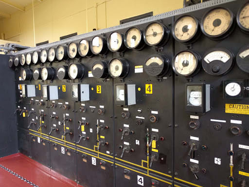
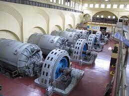
Many years ago I had the opportunity to tour what may have been one of the last major hydro plants in North America under complete manual control.
The individual unite typically ran at either 10% output or 90% output.
At 10% output, the generators stayed warm and dry and remained synchronized to the grid, available for rapid dispatch.
While I was there, there was only myself and a lone operator in the station, the phone rang (POTS).
It was load control dispatch with the message;
"Take unit #4 to 90% output."
The operator turned a selector switch on the control panel.
A hydraulic valve opened and a large hydraulic cylinder controlling the water gates started to slowly extend.
The hydraulic pump was driven by a small Pelton Wheel.
As the output increase,the power factor dropped.
The operator then went to a rheostat control knob.
Turning that increased the current to the field of the exciter. This raised the excitation and the PF improved.
The operator went back to the hydraulic control switch and increased the water flow, while watching the dropping pF.
The operator reiterated these steps 4 or 5 times until the set was at 90% output.
Complete manual control according to voice commands or a Plain Old Telephone System. (POTS)
[/anecdote]
I hope that I have covered the basics enough that you may apply the knowledge to your individual situation and to the control equipment that you have available.
PS; CR has spent a career operating generating plants.
Respect any advice he may share with you.
In the event that there may be an apparent disagreement between CR and myself, it may be more a case of misunderstanding, or I may be learning something new.
2016-06-13_fpzosp.jpg

MACHINE_FLOOR_mg9dvt.jpg


--------------------
Ohm's law
Not just a good idea;
It's the LAW!
 
My take: as noted in the thread above by bacon4life, what would determine the separate regulators are needed is the allowable voltage range of the gen, and what is the allowable voltage range of the line, and consider any VARS present or required that would boost or voltage the gen side voltage.
If the gen voltage has a smaller allowable range than the utility plus any buck/boosting due to VARs you will need regulators.

In my state, the distribution feeder voltage is allowed plus or minus 5%. Per IEEE, a typical generator voltage range is plus or minus 5%. If a large amount of vars is not available or required (such as miles of underground cable, or a power factor requirement, say to boost voltage when the grid is at 5% overvoltage) a separate on-load voltage regulator wouldn’t provide much benefit.
On the other hand, a large wind farm with miles and miles of underground cable providing capacitive VARs with induction motors in the turbines potentially could boost the voltage above the 5% allowed at low loads, damaging or tripping the turbines offline. There a regulator/tap changer would make sense.

Historically, at least in The US, conventional synchronous machines almost never had tap-changing regulators, early wind farms always had them (typically on load tap changers in the transformer). With modern inverter based distributed resources that are trending toward mimicking synchronous machine performance, I am not sure those OLTCs/regulators are needed anymore - at the wind farm where we have the inverter based wind turbines the tap changer almost never operates.

Hopefully this is somewhat useful information for you.

Waross, when I joined my company in 2007/2008 we still had two small hydro plants from 1898 and 1904 that were entirely manual - I ended up putting the very first PLC in one of them (as well as the first sync check relay believe it or not) Watching the operator put a unit online entirely manually was pretty cool and educational for a new engineer.


Status
Not open for further replies.
Back
Top