Continue to Site

Eng-Tips is the largest engineering community on the Internet

Intelligent Work Forums for Engineering Professionals

  • Congratulations waross on being selected by the Eng-Tips community for having the most helpful posts in the forums last week. Way to Go!

Use out-of-plane capacity of wall to resist lateral load?

Status
Not open for further replies.

RyanTa

Structural
Dec 29, 2019
7
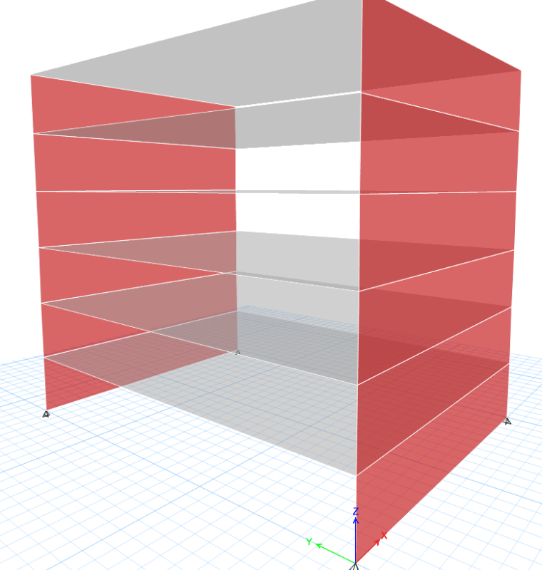
This is a 6 storey building. The walls (200mm thick) run in x directions only. Due to the architectural layout, no shear walls can be arranged in y direction, I might add some internal columns between walls for gravity supports. All floors are flat slab.
My question is, can we reply the out-of-plane capacity of wall to resist the lateral loads? I have never done it this way but cannot explain why it will not work. If we simplify this structure as frame, make the wall(out-of-plane) to slab as rigid connection then it will give you the capacity to resist lateral loads. I have checked the strength of the walls and it is okay. The deflection is also under limit. So it there any other considerations that I miss?

12221_rwttp1.png
 
Replies continue below

Recommended for you

You seem to be describing a Continuous concrete moment frame - sounds feasible -seems like story drift could be a concern though - along with detailing.

Mike McCann, PE, SE (WA, HI)


Hi msquared48, yes with the internal columns it is. However I am more concerned about using the out-of-plane capacity of the wall so the structure here I am talking about is actually using wall out-of-plane capacity alone without internal columns. One thing I find this structure dangerous is once there is hinge generated at the wall-slab connection under earthquake, the structure will be unstable and collapse. But I cannot tell if there is any issue using this structure to resist wind loads if the strength and deflections seem fine.
 
Agree with msquared48.
 
Y-direction would be moment frames, 200thk walls and slabs making up the frames. Looks like you are modelling in etabs, the out of plane bending stiffness will likely need low stiffness modifiers, M11=M22=M12=0.4 (depending on local code requirements). Slabs should also have similar modifiers to the bending stiffness.
 
May I ask why out-of-plane stiffness need to be modified? I can understand in most cases normally we modify them to avoid massive reinforcement and under earthquake we allow the wall to crack but in this case, do we really need to or can we really modify them? The out-of-plane capacity is the only thing we use to resist the wind loads, if we modify them, does that mean we allow the walls to crack under wind load?
 
I doubt with only 6 floors on the walls they are going to have a high permanent compression to say they remain uncracked under lateral loads. Even uncracked walls require a stiffness modifier of 70%, cracked walls require 35%. These walls look like they are going to be behaving as a flexural member so I believe the stiffness modifier should be closer to the cracked value.
 
You're mentioning earthquake, so check if your code allows the use of such system (some, for example eurocode, don't allow frames without beams). Secondly, how do you plan to dissipate the energy? Plate bending? What about the bottom of the wall, I guess you'd need to confine the whole width of the wall, right? How do you plan to avoid shear failure in plate? I'm not as experienced as a lot of other guys here, but this doesn't look like a good idea to me.
 
What are your proportions? It looks to be about 3m high x 8m long.

What is your plan for the slab-to-wall connection?
 
Is this a theoretical building for a course or something?
 
What kind of 6 storey building has absolutely no walls on 2 sides? Is it a big storage shelf or something?

Rod Smith, P.E., The artist formerly known as HotRod10
 
Can be curtain walls on both ends.
 
Woof. Agree with @BridgeSmith. No walls on 2 sides? You're gonna be floppy in one direction regardless of how the analysis model works.
 
Your model looks too slim to avoid sway mechanism, the slab-wall joints can be very difficult to handle. I'll try much stiffer walls, ideally the walls shall be connected by stiff mat foundation with over hangs, so it will looks like an inverted double tee, which is very stable. Just thinking and speak loud.
 
It is a real case in Australia. It is 3m high x 14m long I have checked the code and couldn't find anything regarding whether this kind of structure is forbidden or not but I have never designed it this way and am not comfortable with it. There are not walls on both sides because they are both curtain walls. I can arrange one or two short walls above first floor but they have to be transferred on the first floor. On the ground floor it will be only small internal columns or walls in X direction without any walls in Y direction. I also have some problem understanding modifying the stiffness as rscassar mentioned. Reducing the stiffness will gives me larger deflection, which is safe but won't be it unsafe for the strength design? If we reduce the stiffness the moment will be reduced and we design the reinforcement accordingly, won't it be unsafe? For this structure, once there are hinges generated at wall-slab connection, doesn't that mean it will be unstable?
 
Do an exploratory analysis to find the weakness and level of difficulty. Don't be bothered with absolute stiffness at the first try (relative stiffness is suffice for the purpose).
 
Can a stair/elevator shaft provide the shear resistance? That would be better I think.
 
bones206 raises a very good view point. Also, many modern curtain wall buildings have successfully add bracings at perimeter, either hiding from view by tainted glasses, or expose to view to add aesthetic value of the buildings. Something to think about.
 
Even if it did work at a first level analysis (and I doubt it would as far as allowable drifts go), I would think it would be very susceptible to P Delta effects. Be sure that is looked at.


This structure is actually part of the building, There is stair and elevator core but it is on the other side. What happens here is the architect cut two big rectangle out of the building at the middle to get lights. So it looks like a I shape building. And as the connection between these two blocks are weak and I would treat them as separate diaphragms.
 
Status
Not open for further replies.

Part and Inventory Search

Sponsor