Continue to Site

Eng-Tips is the largest engineering community on the Internet

Intelligent Work Forums for Engineering Professionals

  • Congratulations IDS on being selected by the Eng-Tips community for having the most helpful posts in the forums last week. Way to Go!

Using a complex blade surface as datum feature 1

Status
Not open for further replies.

Yuyu28

New member
Sep 6, 2019
15
Hello all,

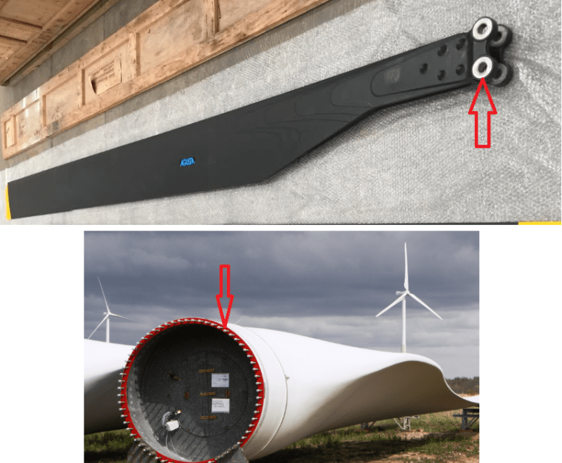
Imagine a carbon-fiber rotor blade that is manufactured by laminating the layers on an inner mold, and cured inside an outer mold that will determine the outer, complex aerodynamic surface. The blade is then trimmed at the root and at the tip, forming two planes that, theoretically, are perpendicular to the span direction. Then a pattern of holes is drilled; each hole's axis is normal to the outer aerodynamic surface, so each one has a different direction.

What would be a correct way acc. to ASME Y.14-5 (2009 or 2018) to determine the position and the form of the trimming planes and the hole pattern? In principle, the 3D CAD model is leading, but my company still wants tolerancing on 2D drawings.

I thought of defining the whole outer surface (excluding the root and tip planes) as a datum feature A. According to Fig. 4-3g (2009), that should restrain the 6 DOF; am I correct?

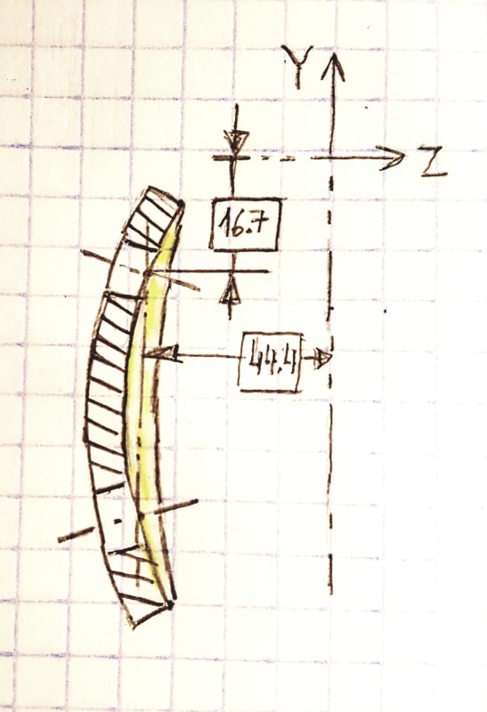
Then the root planes could be defined with a profile tolerance without any reference, their theoretically exact positions given by the 3D CAD model.

But the pattern of holes is more problematic. Their axes are not parallel to the root/tip planes. The only way to unequivocally define their position is in the 3D CAD model. Can I just give their positional tolerance referenced to datum A (meaning that the holes are normal to the surface), without any TED? Would I need to define a coordinate system and use it to position the holes with TEDs, as in Fig. 4-28 (2009)?

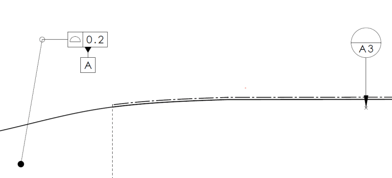
By the way, in Fig. 4-28, what does the lower profile tolerance in detail A point to? It looks like a very thin edge, but I have no idea what it is exactly.
 
Replies continue below

Recommended for you

Normally one would specify the mounting surfaces and the mounting holes as the datum features and then specify the contour of the surface of the blade relative to them; this is the way the blade is located in the mount. Back-driving the process seems like it will make no one happy. Consider adding stub pins to impress exactly where the cuts are to be made into the mold.
 
Yuyu28,

Yes, the profile in Fig 4-28, Detail D is pointing to the edge of the part. I think the all around symbol should be deleted from the leader, but otherwise the tolerance spec seems OK to me.

If the rotor is relatively long, and the mounting surface short, then I agree with you, that it would be best to use the entire outer aerodynamic surface as datum feature A. To simplify establishing the datum reference frame, would the method shown in Figure 4-54 (2009) work?

Depending upon how well the aero surface constrains translation in the direction normal to the planar surfaces at the root and tip (I'm guessing that the aero surface has minimal capability to constrain this translation), it may work best to use one of those planar surfaces as a secondary datum feature (probably the one at the root), to constrain that final translation. If that is the case, and if the aero surface has any capability to constrain that translation, then a customized datum reference frame per paragraph 4.22 will be needed, so that translational constraint can be explicitly assigned to the secondary datum feature.

I think there are several advantages to showing coordinate axes to represent the datum reference frame. One advantage being that additional coordinate systems can be specified, with sequentially numbered axes (X,Y,Z, then, X2,Y2,Z2, then X3,Y3,Z3, etc) with one axis of each coordinate system oriented such that it is parallel to a mounting hole axis. I think all coordinate systems should have the same origin, with basic angles shown to define the rotations needed for each coordinate system relative to the initial datum reference frame. All of these coordinate systems really are the datum reference frame, since only angular TEDs define the orientation of each from the initial datum reference frame. These coordinate systems provide a clear means of showing the needed TEDs to each hole, and also a clear means of reporting the locations for each hole.

If one planar surface is the secondary datum feature then it would need a perpendicularity or profile of a surface tolerance that references the primary datum feature. The other planar surface and the aero surface would each need a profile of a surface tolerance that references both the primary and secondary datum features. Basic dimensions for the aero surface could come from the 3D CAD body and, to make this easier for inspection, a table of measurement points for the aero surface with columns for X, Y, Z, i, j, k could be shown. These values can then be used directly in a CMM program, so the probe will be driven down each surface normal vector to each specified measurement point.

Dean
 
Yuyu28,

How about the constraints shown in ASME Y14.5-2009 Figure[ ]4-42. They actually are discussing the constraint of a flexible part, but it does show a complex, non-orthogonal shape, and datum targets.

--
JHG
 
Dean said:
If that is the case, and if the aero surface has any capability to constrain that translation, then a customized datum reference frame per paragraph 4.22 will be needed, so that translational constraint can be explicitly assigned to the secondary datum feature.

Shouldn't figures 7-49 and 7-29 in the 2018 standard (4-42 and 4-28 in 2009) have a customized datum reference frame too, for the same reason?

To the OP - are you sure the mounting surfaces can't be used as datum features? If they are reliable enough to mount a blade to a rotor mechanism...
 
Burunduk,

In 4-28/7-29 datum feature A could be spherical, so a customized DRF may not be needed. For 4-42/7-49 datum feature A is much less likely to not have some capability to constrain a degree of freedom that datum feature B or C is intended to constrain, so I think it's fair to say that a customized datum reference frame should be used.

Astute observation on your part. Thank you for bringing this up. It's always good to be shown things that are being missed.

Dean
 
They don't appear to need such a thing in Fig. 4-42 as the point of a restrained control application is to force the part to conform to the datum feature simulators and not to allow these simulators to provide float. The details of how that restraint occurs is controlled by the requirement spelled out in the restraint note.
 
3D Dave,

Using a customized datum reference frame for Fig 4-42 would better describe what is happening when the restraint is applied, unless the hood shape within the datum target A areas is cylindrical.

Dean
 
Dean, what is happening is the hood is deformed by the applied loads. Are you suggesting they provide the elasticity matrix that describes the resulting stress field based on the deformation? I'm all for that, I'd guess a 10,000 X 10,000 mostly diagonal matrix would cover it nicely but I think that's outside what a customized DRF is for.
 
The underlying reason is that the restraints overconstrain the hood; that is, the various datum references apply more constraints than the 6 required and can likely supply 4 at each datum target ocation. The exact nature of what they do and their relevance is in the constraint application Work Instruction (WI) listed on the drawing. These will override the rules generally used for rigid bodies typically covered in the D&T standard.
 
Dean,
Glad to be of any help.

Can I conclude from your response regarding fig. 4-28/7-29, that datum reference A[BSC] - being spherical, is intended to constrain 3 translational degrees of freedom and the pattern of twelve holes referenced as B at MMB constrains 3 rotations for the profile tolerance? With such shallow depth and gradual curvature, is there any confidence it will work this way? Could the pins that should mate with the twelve holes constrain two translations better than the spherical surface anyway?

Actually, I interpreted the feature to be nominally cylindrical, not spherical. I think that if the left-hand view is a "section view" (which is more common than "section cut") then if the elliptical contour of the part was cut out of a spherical sheet, the section view should have looked something like the image below.
See the marked up surface in yellow which is missing from the figure.

20200707_222732_k8q3nc.jpg
 
3DDave and Dean Watts,

I brought up figure[ ]4-42 because it shows datum targets applied to a complex surface. The flexibility and applied forces are irrelevant to this discussion.

If this were my rotor blade, there would be a set of orthogonal mounting surfaces I would use as datum features. The funny, curved surfaces would be controlled by profile tolerances. This has to be the simplest, most logical way to do this.

--
JHG
 
drawoh,
The flexibility and applied loads are being discussed because Dean addressed the manner in which constraints of degrees of freedom should be specified (if overridden) or implied if the complex aerodynamic surface of the blade is used as a datum feature as the OP intended. In that case, as Dean noted, a customized datum reference frame might be useful. I suggested that the same issue might be relevant for fig. 4-42, which you mentioned for a different reason.
It's a side topic of sorts but I don't think it detracts from the responses that were provided to the OP on his specific problem.
 
As noted, requirements in the restrained condition are specified in order to evaluate conformance to requirements when the part is deformed the same way as it is in its functional assembly.
Does a restraint per the restraint note always overrides the default degrees of freedom constrained by each datum reference? I wouldn't say so. A lot depends on the forces applied by the restraints and how they are applied.
For the hood shown in fig. 4-49 (2009), datum feature A should restrain translation in Z and rotation about u and V in both the restrained and the unrestrained conditions, and may influence translation in X and Y both in the restrained and unrestrained conditions although not reliable at being able to properly constrain them.
 
Thank you all for your answers, and apologies for the late reaction.

When you all talk about the mounting surface, what exactly do you refer to? Would it be the surface on which the blade is positioned in order to check the tolerances? If so, could the bottom half of the mold used as a mounting surface? Otherwise, AFAIK the blades are mounted "manually", maybe with assistance of an overhead crane and straps.

3DDave, thanks for the idea of using stub pins in the mold; I will keep it in mind.

Dean, I would prefer to avoid using a customized DRF. I am using ASME Y14.5 as a guide, but in theory my company works with ISO 1101. In the ISO 1101 (2017) I cannot find any use of a customized DRF. Maybe it is defined in another of the myriad of GD&T ISO standards, but unfortunately I only have access to 1101. Regarding the constrain in the span direction, the aero surface should be able to do that since it is tapered from root to tip.

drawoh, the problem with using an approach like that is that I don't know how the blade will deform in a restrained condition with a few clamping/pickup points. Also, I am not used to tolerancing under restrained conditions, and I don't have access to specific ISO standard where that is defined, so I think using the free state would work better for me. I believe that using the mold as a mounting surface would be a good approach to have a free state; correct me if I'm wrong.

If I do define the aero surface as datum feature A, would it be incorrect to also define datum target points on that surface? See screenshot below.

On the topic of fig. 4-28/7-29, I, like Burunduk, also interpreted that the true geometric counterpart of datum feature A (A1?) is a cylinder.

Profile_as_datum_and_datum_target_li6gd5.png
 
When you all talk about the mounting surface, what exactly do you refer to? Would it be the surface on which the blade is positioned in order to check the tolerances?

When we talk about mounting or functional surface(s) it is typically the surface(s) on which the part is literally mounted during assembly or possibly those surfaces which are utilized/contacted during use. There are some exceptions to that when you might want to use some other surface as a datum feature, but that usually a good starting point. This way the tolerances applied to the other features on the part should be driven from the way the part functions and assembles.

In addition to not necessarily reflecting your assembly condition or function, the complex feature of the rotor surface(s) will likely make for a problematic datum feature. It will almost certainly preclude hard gauging and I think you'll find evaluating contact with your simulator (or whatever the equivalent is in ISO) - virtual or otherwise - to be a non-trivial endeavor unless you utilize datum targets.

Below is an example of the mounting surfaces on rotor blades. On the upper blade it would be the flat flange surface(s) and the bolt holes, on the lower blade it would be the flat flange surface and possibly the piloting ID or OD (the threaded holes around the perimeter might or might not be used for clocking).

rotor_blade_3_tzwg9d.png


If I do define the aero surface as datum feature A, would it be incorrect to also define datum target points on that surface? See screenshot below.

To attach both a datum feature symbol as well as datum target points to the same surface with the same letter designation? Yes, it would be incorrect as it would be unclear what you mean when you refer to datum feature A.

I am using ASME Y14.5 as a guide, but in theory my company works with ISO 1101

......in theory? What is specified (or do you plan to specify) on your company's drawings? That is what you should go by.
 
Yuyu28 said:
If I do define the aero surface as datum feature A, would it be incorrect to also define datum target points on that surface? See screenshot below.

It is OK to use a datum feature symbol and datum target symbols applied together to the same surface with the same letter only if the datum feature symbol is attached directly to the surface, see example Fig. 4-53 in Y14.5-2009, datum feature A. In that case the datum feature symbol is shown for clarity to make identification of the surface to which the datum targets apply easier. It is incorrect when the datum feature symbol is associated with a profile tolerance as in your screenshot. As it is in your screenshot, the entire surface which is controlled by profile is supposed to be used for deriving the datum, which contradicts the idea of using datum targets.
 
Burunduk,

I would say the notation as shown in Y14.5-2009 fig 4-53 is bad practice. This has been explicitly changed in 2018 to attach the "A1,2,3" and "B1,2,3" next to the datum feature symbol in fig 7-64.
 
chez311,
I agree that the notation in fig. 7-64(2018) is better than in 4-53(2009).
Probably in OP's case the datum feature symbol is not needed since the aero-surface is by far the largest surface on the part and it won't be necessary to clarify what the targets apply to.

All this should be much less significant to the OP than considering the use of the mounting surfaces (functional features for assembly as was clarified), as the datum features.

Yuyu28, you mentioned that the 2D drawing has secondary significance in your company and that the model is leading for product definition. Does the model include tolerances?
 
Status
Not open for further replies.

Part and Inventory Search

Sponsor