Continue to Site

Eng-Tips is the largest engineering community on the Internet

Intelligent Work Forums for Engineering Professionals

  • Congratulations SDETERS on being selected by the Eng-Tips community for having the most helpful posts in the forums last week. Way to Go!

Using Aluma Beams in Reverse

Status
Not open for further replies.

Enable

Structural
Jan 15, 2021
788
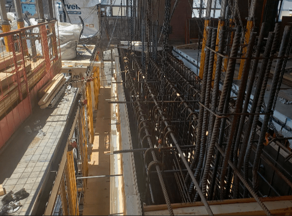
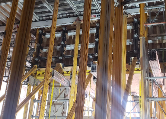
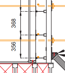
I have a vertical formwork design where I would like to use aluma beam whalers, and for constructability reasons I would like to invert the beam. That is, large side on loading member and small nailing edge on support.

The literature on the beams doesn’t give anything on this and I haven’t been able to get through to engineering. It’s a homogenous material so you’d think I shouldn’t have any concerns about this but since I don’t design with aluminum here are my thoughts (FYI span is 1.2 meters so these beams should be shear controlled and the buckling concerns may be moot):

A) By inverting the beam I am changing the primary compression flange (though as a continuous beam it’ll switch). If the beams have local buckling issues inverting the beam may not make the span load tables applicable. Same doubles for brace location requirements to deal with LTB (doubtful but still)

B) Bearing area is significantly less on the nailing strip side

Anecdotally, I have formed using inverted alumas before when in a pinch. But never with the kind of loads I am designing this for. Time is essential here so any thoughts would be much appreciated!

Alumas_en0iy2.png
 
Replies continue below

Recommended for you

While it is unclear exactly what you are trying to accomplish (i.e. is the detail a plan or section),

a) In the US, aluminum beams for concrete forming and shoring are available in many different depths and profiles. Are you referring specifically to the 6 1/2" deep Aluma brand aluminum joist? I do have old literature on some versions of these joists that have different allowable bending stresses whether the moment is positive or negative.
b) If the intent is to use double joists as a walers (supporting the joists, and spanning from tie to tie), I would be very hesitant, especially due to the local bearing/reactions at the tie locations. If manufacturers/suppliers could find a way to use the joists as walers, they wouldn't have a separate heavier product (typically double channels) for these conditions. Plus these joists have wider flanges, which would make tie plates an issue. I would try and find dedicated formwork walers, or maybe even consider double loose steel channels or even deeper lumber.
c) If the issue is just the orientation of the aluminum beam used as a joist (supporting the sheathing, spaced relatively closely), I would be concerned somewhat about the connections between various components. The "bottom" edge of most aluminum joists include a continuous raceway to allow for connections, while the "top" includes an integrated wooden nailer for plywood. Flipping the orientation could create challenges in the connections.
d) If you still wanted to flip, you could potentially add additional lateral bracing to mimic the bracing typically provided, but I am not sure how you would justify the bearing/reaction condition, short of getting information from the manufacturer.


Yes, 6.5" deep from aluma systems. Any literature would be helpful! I'm working with an existing design done by the contractor that I was brought in partially through to help review. So I am trying to make what they have / the existing setup they intend to use work.

The setup is: formply + stud wall + single aluminum whaler + HSS strong-backs. The ties are threaded rod. They compress the strong-back and in turn the strong-back holds the aluma beam. The aluma beams check out quite nicely given the allowable loads in the table I linked to above. My concern is how applicable they are given the inversion of the beams.

I'm thinking of adding steel plates, secured to the nailing strip with screws via pre-drilled holes, to increase bearing area. Plus add the lateral bracing at points as you note.

EDIT - that is a section through the longitudinal direction
 
So for example,

The typical way around the actual aluminum width on the bottom flange is 4.5" (approx). Typical for bearing for steel and such is 1.75" lets say, so that's 8in2 of bearing area. The topside of the aluma has a 3.2" head but only about 1.5" of that is aluminum. So if I equivalate I would need the following

Length of Bearing = 8in2 / 1.5in = 5.333"

Seems like I can make this work with a 6" steel plate fastened to the nailing strip that bears against the HSS.

Thoughts?
 
I believe that the true Aluma System joist has a bottom flange width of 5", not 4 1/2". I would recommend that you try and get the technical data for the exact joists you would be using from the supplier, and they should have the required technical information (or perhaps you can at least find a technical representative for the manufacturer.

And I guess I still don't understand the benefit of flipping the joists - I would think that the formply and stud wall would connect better to the wood nailer side of the joist, as opposed to the bottom flange of the joist (though in my experience, the condition of the wood nailer are often questionable). Most aluminum joist suppliers have specific clamp components that can be used to attach to the top and/or bottom flange of the aluminum joists, which are often significantly stronger then connection to the nailer.

 
The aluma system is a 5" base but has a 1/2" (ish) cut-out so it would not count in my equivalent bearing calc. The benefit of flipping the joists was for ease of holding up along the sides of these long beams (they measure 26' long, 7' high, 5' wide). He could more easily cleat the flange to the formwork than he could the nailing strip side.

Update
In case anyone was wondering, we poured today and she held like a tank. To be a bit more comfortable with the flipping of the alumas beams we braced the compression flange every 4' on the form side with spiked 2x4s, and on the strong-back side we sandwiched the bearing plates with 3/4" ply ramset into the strong-back. 8" steel bearing plates were secured to the nailing strip at the strong-back via simpson strong-tie structural screws.

Here is prior to closing the deck

P1_r5rci8.png


Here's it all together

P2_mwz9os.png

P3_hevwng.png
 
Status
Not open for further replies.

Part and Inventory Search

Sponsor