Josh Blank
Industrial
Hello, long time listener first time caller.
My foundry uses a water immersion tank to leak test brass valves that we cast and machine. Temporary plugs are installed into the valve and 20psi air is ported into the valve through a special plug. If air bubbles through the cast/machined surfaces, the valve leaks and we throw it back in the furnace to try again.
The bane of my existence is that we use a male NPT plug with an O-Ring that seals on the lead thread chamfer. The NPT thread OD is a little overcut so the fit is a little loose (prevents damaging the threads, facilitates ease of install/removal). This works out pretty well for how sacrilegious it is. The only problem is that where the lead thread actually starts (where the first thread overlaps and becomes the second thread) we sometimes get some air that bubbles through, and the valve is incorrectly deemed a leaker.
We are looking for a way to improve on this design. We cannot seal on the face of the valve where this port is because we don't want to mask any leaking that could come through the face (we previously sealed on the face, customer complained about leakers in the field). We've tried using plastic NPT plugs to seal on the threads, and those worked great for maybe 15 cycles before they got too deformed/beat up. We would prefer not to use any pipe dope / tape since we leak test hundreds of these valves per day and the lost time would not make up for the occasional false leaker. Our rate of false leakers is maybe 1%, but I've never personally seen one so it may be lower than that.
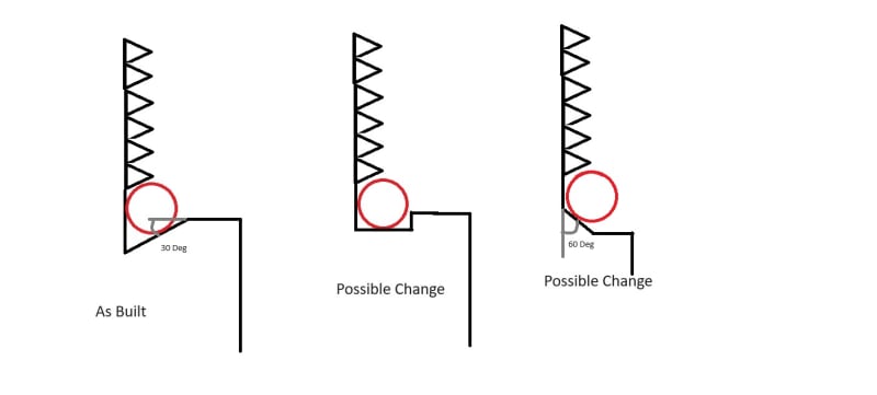
The O-ring currently rests in a relief that's cut at about a 30 degree angle (parallel to female NPT thread). We've been kicking around the idea of changing that relief to be either a full square or a 60 deg chamfer to match the female NPT threads. Does anyone think that would actually help seal on the thread overlap, or just wishful thinking?
And then the big ask here is if anyone has any better idea for a quick-change, full seal NPT thread given the constraints of this process? I am pretty much at the point of collecting up all the potential false leakers, and doing the test again with a real NPT plug and pipe dope.
Please forgive my MS paint sketch, we only have one CAD license.
My foundry uses a water immersion tank to leak test brass valves that we cast and machine. Temporary plugs are installed into the valve and 20psi air is ported into the valve through a special plug. If air bubbles through the cast/machined surfaces, the valve leaks and we throw it back in the furnace to try again.
The bane of my existence is that we use a male NPT plug with an O-Ring that seals on the lead thread chamfer. The NPT thread OD is a little overcut so the fit is a little loose (prevents damaging the threads, facilitates ease of install/removal). This works out pretty well for how sacrilegious it is. The only problem is that where the lead thread actually starts (where the first thread overlaps and becomes the second thread) we sometimes get some air that bubbles through, and the valve is incorrectly deemed a leaker.
We are looking for a way to improve on this design. We cannot seal on the face of the valve where this port is because we don't want to mask any leaking that could come through the face (we previously sealed on the face, customer complained about leakers in the field). We've tried using plastic NPT plugs to seal on the threads, and those worked great for maybe 15 cycles before they got too deformed/beat up. We would prefer not to use any pipe dope / tape since we leak test hundreds of these valves per day and the lost time would not make up for the occasional false leaker. Our rate of false leakers is maybe 1%, but I've never personally seen one so it may be lower than that.
The O-ring currently rests in a relief that's cut at about a 30 degree angle (parallel to female NPT thread). We've been kicking around the idea of changing that relief to be either a full square or a 60 deg chamfer to match the female NPT threads. Does anyone think that would actually help seal on the thread overlap, or just wishful thinking?
And then the big ask here is if anyone has any better idea for a quick-change, full seal NPT thread given the constraints of this process? I am pretty much at the point of collecting up all the potential false leakers, and doing the test again with a real NPT plug and pipe dope.
Please forgive my MS paint sketch, we only have one CAD license.
")