clbackus
Mechanical
- Nov 5, 2020
- 4
Hi,
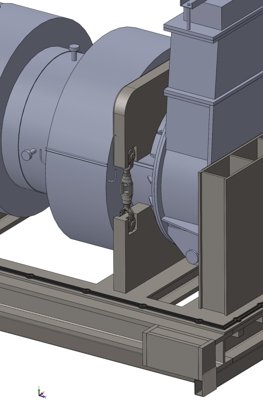
I am trying to establish adequate torque on essentially a turnbuckle assembly which has two jaw fittings on either end. The nominal torque needed is around 1500-1800 ft-lbs, the nominal size on the threaded turnbuckle rod is 2.5". The issue is the space I have to work with and I cannot use a standard socket with this application. Therefore, I have found an appropriate crows wrench adapter (3-7/8" across flats) to engage the hex on the turnbuckle body. The turnbuckle is being used to essentially clamp down on two large saddles, one upper saddle which sets on the top of a large cylindrical payload and one lower saddle which is welded to the floor of our shipping container (see example image). What I am concerned with is using a manual torque multiplier with the crowfoot wrench, since normally you need a reaction bar for the multiplier. However, in this case with the crowfoot wrench, we need the multiplier wrench to turn, which would mean the multiplier body would need to move as you are torquing the drive. Is this feasible to do? Is it even possible for the operator to hold the multiplier? Two operators perhaps, with one applying the input torque? I considered a ratchet binder turnbuckle arrangement which has the ratchet arm built in, but the problem with that is I don't know how much torque is being applied (thus clamping load) and it's not nearly enough anyway. Other solutions? Thank you in advance for your assistance!
I am trying to establish adequate torque on essentially a turnbuckle assembly which has two jaw fittings on either end. The nominal torque needed is around 1500-1800 ft-lbs, the nominal size on the threaded turnbuckle rod is 2.5". The issue is the space I have to work with and I cannot use a standard socket with this application. Therefore, I have found an appropriate crows wrench adapter (3-7/8" across flats) to engage the hex on the turnbuckle body. The turnbuckle is being used to essentially clamp down on two large saddles, one upper saddle which sets on the top of a large cylindrical payload and one lower saddle which is welded to the floor of our shipping container (see example image). What I am concerned with is using a manual torque multiplier with the crowfoot wrench, since normally you need a reaction bar for the multiplier. However, in this case with the crowfoot wrench, we need the multiplier wrench to turn, which would mean the multiplier body would need to move as you are torquing the drive. Is this feasible to do? Is it even possible for the operator to hold the multiplier? Two operators perhaps, with one applying the input torque? I considered a ratchet binder turnbuckle arrangement which has the ratchet arm built in, but the problem with that is I don't know how much torque is being applied (thus clamping load) and it's not nearly enough anyway. Other solutions? Thank you in advance for your assistance!