Continue to Site

Eng-Tips is the largest engineering community on the Internet

Intelligent Work Forums for Engineering Professionals

  • Congratulations waross on being selected by the Eng-Tips community for having the most helpful posts in the forums last week. Way to Go!

Using Plasticity definitions in Nitinol UMAT - finding some interesting problems 1

Status
Not open for further replies.

ryankb

Bioengineer
Oct 5, 2017
26
I've been noticing some really odd problems with the nitinol material definitions when trying to use plasticity. I attached my model, but I'll describe it as well.

I have a simple stent structure going through a 3 stage expansion with anneal/crimp/deploy/load. During the crimp step it sees very high stress/strains. I estimate I should be somewhere in the 12-13% strain, so I switched from the elastic model to plastic model. The elastic model solves just fine by the way. When I put in the "real" values of my tensile data, the model failed. When I simplified and artificially "softened" the material everything solved just fine. Next, I re-ran it with another very simple plastic definition (only 3 data points), but with higher stress-values (stiffer), and this failed. It seems like plasticity model works when the nitinol is relatively soft, but if it can withstand higher stress levels at UTS, the model fails on me.

Has anyone else seen this before? I confirmed the same behavior on another model I've been working on lately as well.
 
Replies continue below

Recommended for you

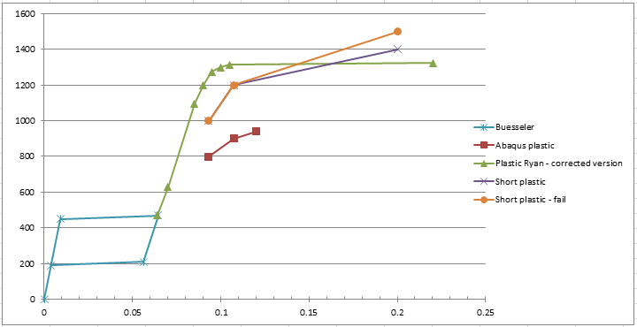
Here's a quick excel graph of the material definitions and how they work/don't work....

plastic_definitions_yi8uk9.png


Focus on what's to the right of the flag...
Green: actual data. When I put the datapoints in, it fails most of the way through the crimp step, but typically somewhere around the 11-ish% strain mark.
Red: This one works, though the maximum stress in the completed model show up above 1200 MPa, which is outside of the material definitions, despite the strain staying below the maximum allowable in this definition.
Orange: This one also works - this doesn't match up with the data well. I was just trying to mimic the "style" of the red plot, but closer to the stress values of the real data.
Purple: This simulation fails at around 92% of the way through the crimp step. It's so close to the orange plot, I don't see how this one keeps getting cutbacks and stops but the orange one is fine.

Perhaps the larger question I should be asking - do I even bother with the plastic model? Is it generally accepted to not use the plastic definitions? Physically I don't think that without plasticity I will see agreement, but I also don't know if the plasticity is even working to know if it's correct. How do I check more effectively? Plastic strains? Martensite transformation? (I don't know how to check either in Abaqus though).
 
I'll take a look at your model when I have a chance later.

As a first step you should create a single element model and subject it to uniaxial tension. This model should run in seconds and you can extract the stress vs. strain response and compare to your test data. This will allow you to figure out if your material model has been calibrated/defined correctly.
 
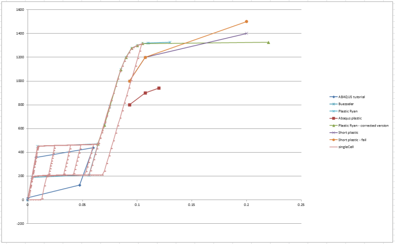
The single element model shows good agreement with the data:
singleCell_jv8gsv.png
 
can you create one plot where you overlay stress-strain from your superelastic-plastic single element to your uniaxial test data?
 
That is actually what is plotted above. The pinkish color is the single element test. It overlaps the graph above so it's difficult to see the underlying tensile data
 
sorry i haven't had a chance to look at your model.

is your material model calibrated to actual true stress-strain data? the plastic section looks very flat and there doesn't seem to be much hardening? a bit surprising.

To answer your larger question - I don't think you need to use the superelastic-plastic material model. Generally for a self-expanding stent you want to avoid yield and permanent plastic deformation. You know that plasticity occurs above specific strain levels so that's what you design to. This can be done quite well with the superelastic material model. At the moment, the strains you see in the crimp step are extremely high. your mesh is also quite coarse so they are likely to get even higher if you run a convergence study. I think you should redesign your stent and open up the radii at the crowns. Other options would be lengthening the strut and reducing width/thickness.

Finally, you can request the state-dependent variable (SDV) output in the step module. The variables are as follows:

SDV1 – 6 Linear elastic strains
SDV7 – 12 Transformation strains
SDV19 Equivalent transformation strain
SDV20 Volumetric transformation strain
SDV21 Fraction of Martensite
SDV22 Equivalent uniaxial tensile stress
SDV23 Equivalent uniaxial tensile transformation strain
SDV24 Equivalent uniaxial tensile total strain
SDV26 – 31 Plastic strains1
SENER, ELSE, ALLSE Linear elastic strain energy variables2
PENER, ELPD, ALLPD Transformation strain energy variables2
 
I too was pulled away from this simulation early this week, so don't worry.

Yes, the material is calibrated. The test data and single-element data are completely on top of each other. I'm assuming you meant the elastic section is quite flat? That is quite typical of the nitinol and processing being used here. The plateau's should be very flat.

While I do agree that it is best to design a device such that it never sees the plastic region, this unfortunately doesn't always happen. The model worked on here is part of a larger study looking at multiple input/output relationships. This is merely one data point of a larger set, and it is a necessary data point in order to create a good model. The design options you mentioned are a likely output, but I'm using a more sophisticated method to determine the exact dimensions needed based on the output and their interactions.

For now, I'm just ignoring this one data point and have been paying for it with a poor output. It still puzzles me why/how the plasticity definitions aren't simulating correctly in this case.
 
I was referring to the plastic section of your stress-strain curve - from 10% strain onward. its hard to tell where your test data ends but the plastic region of your curve is very flat (i.e. no hardening) which is unusual. At what strain does your test data end? did you test to failure? what was the failure strain? have you looked at the forces required to crimp your stent up to the point that the analysis fails? are they realistic? Your problem may not be the material model - like you said, single element results overlay perfectly so it seems to be working fine. it may be that what you are attempting to model is not realistic.
 
Status
Not open for further replies.

Part and Inventory Search

Sponsor