Continue to Site

Eng-Tips is the largest engineering community on the Internet

Intelligent Work Forums for Engineering Professionals

  • Congratulations KootK on being selected by the Eng-Tips community for having the most helpful posts in the forums last week. Way to Go!

using regular wire for a thermocouple connection 7

Status
Not open for further replies.

PaulKraemer

Electrical
Jan 13, 2012
145
Hi,

In the diagram below going from right-to-left, I have a type-J thermocouple mounted inside what I describe as the "Applicator". Two conductor Type-J thermocouple cable is used to connect the thermocouple (+) and (-) leads to pins on the 9-pin connector. Regular wire (not thermocouple wire) is used inside the heated hose (which is about 12 feet long) to connect the thermocouple signals ((+) and (-)) to pins on the sixteen pin connector. I have to make the connection to get the thermocouple signal from the 16-pin connector to the Temperature controller. I know that for the best accuracy with thermocouples, it is recommended to use only thermocouple cable throughout the entire connection. This being said, the heated hose is a standard part I buy from a 3rd party supplier. This 3rd party supplier is unable (or unwilling) to supply heated hoses with thermocouple cable for this connection instead of regular wire. With this being the case, as I believe my accuracy will already be compromised due to the connection through the heated hose, I am wondering if there is any advantage to be gained by using thermocouple cable for the connection from the temperature controller to the 16-pin connector. I find it easier to work with regular wire as opposed to thermocouple cable, and I always feel like the crimp-on pins and sockets I use with my 16-pin connectors attach more reliably to #18 AWG stranded wire as opposed to typically #24 AWG solid conductor thermocouple cable. For these reasons, I am leaning towards using #18 AWG stranded wire in this case, but if anyone here tells me there is some advantage to be gained by using thermocouple cable (even though the signal will pass through regular wire inside the heated hose), I will will do so.

Any suggestions or advice will be greatly appreciated.

HeatedHose_e17m07.jpg


Thanks in advance,
Paul
 
Replies continue below

Recommended for you

A metal has an inherent potential curve versus absolute temperature. The challenge is measuring that potential.
A thermo couple works by looking at the divergence of the curves of different metals.

The law of Intermediate Materials

This was originally known as the Law of Intermediate Metals. The sum of all of the emfs in a thermocouple circuit using two or more different metals is zero if the circuit is at the same temperature.

This law is interpreted to mean that the addition of different metals to a circuit will not affect the voltage the circuit creates. The added junctions are to be at the same temperature as the junctions in the circuit. For example, a third metal such as copper leads may be added to help take a measurement. This is why thermocouples may be used with digital multimeters or other electrical components. It is also why solder may be used to join metals to form thermocouples.
This law allows connections between thermocouple leads to be made on terminals of different materials.

What I don't know:
(I don't know but I know how you can find out.)
This is accepted practice with terminal strips but in that case the connections are at the same temperature. In your case, the ends of the copper wires may be at different temperatures. If the temperature/potential curves of the thermocouple extension wires and the copper wires are linear, the circuit should work.
If the curves of any of the wires are non-linear the accuracy may be affected. What accuracy do you require? It may not matter.
The next step? Check and record the Seebeck voltage of the the copper/TC junctions from lookup tables at different ambient temperatures, representative of expected ambient temps. See if there will be a cancellation of the Seebeck voltages at the different temperatures.


--------------------
Ohm's law
Not just a good idea;
It's the LAW!
 
I'm not sure that really matters, since you have the same material on both sides of the junction, and they both have the same thermal drop; when you run through the entire loop, that should all cancel out, mostly. The known-unknown is that the upstream copper/thermocouple wire junctions are not at a known temperature.

Of course, the 9-pin and 16-pin connectors are rife with junctions of dissimilar metals.

TTFN (ta ta for now)
I can do absolutely anything. I'm an expert! faq731-376 forum1529 Entire Forum list
 
The needed cold junction measurement is being taken at the controller (the temperature of the connector terminals) but the cold junction is occurring at the 9 pin connector where the T/C wire transfers to copper. Any difference in temperature between the 9 pin connector terminals and the controller terminals will be appear as an error.

If you are forced to use copper wire then use a 2 wire RTD (Pt100) instead of a thermocouple You can make a one-time measurement/test to determine the positive offset error created by the lack of a 3rd copper compensating wire that takes into account the resistance of the copper hook-up wire. Get a 2 wire RTD, connect it up with copper wire. Make an ice bath slurry with chipped ice (use a blender to chip up ice cubes) and water and stick the RTD in the water and see what the temperature controller reads out. Any value above 32.0°F or 0.0°C is the positive offset error caused by the copper wire lead wires.

Temperature controllers always have a setting for bias or offset - enter the negative value of the offset (if offset is 0.6°F, enter -0.6F as an offset) to eliminate the error due to the copper resistance.
 
With 9 pins, why not use a 3-wire or even 4-wire RTD...but Danw2 has the right idea if you can't spare pins. RTD will be more stable over time than a thermocouple as well.
 
Hi Waross, IRStuff, danw2, and btrueblood,

Thank you very much for your responses. I have used thermocouples many times and knew that they create a voltage that is related to the measured temperature. I had seen the term cold junction compensation before, but I had never heard of the Seebeck Effect and never understood that the voltage produced, rather than corresponding to the actual temperature at the hot end, actually corresponds to the temperature difference between the hot end and the cold end. (Please correct me if I have this wrong). Thank you all for steering me towards a better understanding of what I am working with.

I agree that it would be much better to use an RTD in what I called the applicator. Unfortunately, this applicator is already assembled and difficult to work with. It is basically a two piece (top half and bottom half) block of metal with internal channels through which we pump melted glue. There are internal machined slots in which we have inserted multiple heat cartridges and one thermocouple. There is a small internal chamber that allows for making the necessary wiring connections back to the nine-pin connector, but once the applicator has been assembled and put into service, it is a nightmare to take apart and rewire. Melted glue invariably gets into the wiring chamber and everything gets stuck together. We really only take these apart when a component has failed, and then we just remove and throw away all the components and wiring. Then we clean the wiring chamber thoroughly, install new components, and rewire. The next time I do this, I will definitely use an RTD instead of a thermocouple, but I don't think I can justify doing this right now.

The heated hose we buy as a standard part from a 3rd party supplier. It just includes two copper wires for temperature feedback, so this might preclude me from using 3-wire or 4-wire RTD, but I think 2-wire will even be a big improvement.

For the near term though, from what I understand, the main thing that would make my temperature reading inaccurate would be a difference in temperature between the 9 pin connector and the terminals on my temperature controller. The 9 pin connector is in an air conditioned room at the end of a 3-foot long armored cable coming from the Applicator. I don't think much heat transfers from the Applicator to the 9 pin connector. When I feel the the 9 pin connector while we are running, it doesn't feel warm.

As for the terminals at the Temperature Controller, these are relatively close to the tank in which we melt the glue. (The tank is insulated, however). I will try to come up with a way to measure the temperature in this location, but I imagine it is likely warmer than the temperature at the 9 pin connector. It seems that this can certainly cause a loss of accuracy, but (correct me if I am wrong), it doesn't seem the loss of accuracy would be any greater if I used copper wire from the 16 pin connector to the temperature controller as opposed to thermocouple wire (given the fact that the signal passes through copper wire in the heated hose).

Unless anyone here strongly suggests that I use thermocouple wire for the connection between the 16 pin connector and the temperature controller, I may just wire it with copper wire and see how it works. I don't think great accuracy is critical in this application. We basically just have to heat the applicator enough so that the melted glue flows freely through it while not making it so hot that we damage the glue.

The machine operators should be able to tell if the control they have is good enough to accomplish this objective.

Thank you all again for your help. Any further suggestions or advice will be much appreciated.

Best regards,
Paul


Any thermocouple electronic analog input has to make two measurements to get a reported temperature. The controller adds the CJ temperature measured by an RTD or thermistor, supposedly representing the temperature of its connection terminals (with respect to the freezing point of water), to the temperature calculated from the mV EMF (hot end minus cold end mV) to get its 'reported' temperature, the one that shows up in the display of the controller.

Use copper wire from the 9 pin to the controller. You can make somewhat of a correction in the controller to compensate for the true CJ temp occurring at the 9 pin connector, but the correction will only be as good as the stability of both of the two CJ temps, the measured CJ at the controller terminals and temperature of the 9 pin connector temperature. Anything you can do to stabilize either or both temperatures will help, like keeping AC drafts off the objects by wrapping the 9 pin with some insulation.

With a thermometer, measure the temperature right at the controller T/C connections (under actual operating conditions, doors closed, fans running, whatever). Measure the temperature of the 9 Pin connector. Presumably the 9 pin is cooler than the controller so the controller's reported temperature will be higher than the true temperature by the difference between the controller's terminal connection temperature and the 9 pin connector temperature.

For example, if the controller's terminals are 97°F and the 9 pin is at 71°F, then the controller's CJ is 26°F too high and the reported temperature will be 26° too high. You can use an offset/bias value to correct for that difference by subtracting 26°F, but again, as either temperature drifts with respect to the other, it will result in a CJ error that will directly affect the reported temperature.
 
For the near term though, from what I understand, the main thing that would make my temperature reading inaccurate would be a difference in temperature between the 9 pin connector and the terminals on my temperature controller.
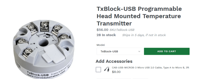
Do you have space adjacent to the 9 pin connector to install a loop powered, temperature compensated, temperature transmitter? Then you may use the wires in the hose to transmit a robust 4-20 mA signal.
Some temperature transmitters are quite small.
Example:
image_wgfmcs.png

Link

--------------------
Ohm's law
Not just a good idea;
It's the LAW!
 
There are only two options.
Either a device like waross suggested and do the temp comp at the first non-TC wire connection.
Or live with the temp not being accurate and simply using it as an indication. The real risk to multiple non-TC material connections in circuit is that if one of the connectors is hotter on one side than the other (+ lead vs - lead) then you will introduce even greater offsets. These cannot be fixed with CJ corrections.

= = = = = = = = = = = = = = = = = = = =
P.E. Metallurgy, consulting work welcomed
 
I think a bigger question is how accurate is the temperature reading need to be? If +- 25 C is ok, then copper will probably be fine.
 
HI danw2, Waross, EdStainless, and DJs,

Thank you for your continued support. Waross's idea of using a loop powered, temperature compensated, temperature transmitter at the location of the 9-pin connector and sending a 4-20 mA signal back through the copper wires in the heated hose sounds like a great way to get better accuracy while avoiding the more difficult task of replacing the thermocouple in the Applicator with an RTD.

I have some room for experimentation on this project. The company I am doing this for has six glue melting units, of which three are currently working. They have asked me to make the three non-working units work like the three working units. After what I have learned in this conversation with you all, lack of attention to proper thermocouple wiring on the working units makes the accuracy of their temperature readings very questionable. I think for starters, I will wire the one I am currently working on as danw2 described in his most recent post (using copper wire from the 16-pin connector to the temperature controller and leaving the hose, applicator, and 9-pin connector as-is). I will try to measure the temperature difference between the two cold-junctions (one at the 9-pin connector and one at the temperature controller terminals) and enter an offset into my temperature controller configuration if warranted.

To DJ's point about whether +/- 25 degrees C is OK, I think it might be. I also think that the working units are likely no more accurate than this. All the temperature controls are doing is keeping a block of metal through which we extrude melted glue (used in label manufacturing) from causing the glue to solidify or become too viscous without damaging it due to excessive heat. I think it is pretty forgiving in the temperature range that accomplishes this. I'll give it a try and see how it works. If I have problems that make me think better accuracy is required, now I have some good options.

I really appreciate all your help.

Best regards,
Paul
 
The transmitter that I suggested may also do RTDs.
Another option may be to mount a thermostat to the metal block and send an on/off control signal back to the panel.

--------------------
Ohm's law
Not just a good idea;
It's the LAW!
 
An easier way to check the existing cold junction error just occurred to me.

The difference between the controller's temperature reading (at the same process conditions) with all thermocouple wire versus the temperature reading with all copper wire between the 9 pin connector and the controller is the CJ error (at that moment in time).

You'd only need about 16-17 feet of whatever type thermocouple wire is in use to temporarily connect the (now-copper side of the) 9 pin connector directly to the input of the controller. You'd have to make sure that the correct polarity/color coding of the thermocouple wire is maintained.

Seemed easier than messing with a thermometer.

I do like the small 2 wire transmitter option though; it uses copper wire by design on the 4-20mA signal side.
 
Hi danw2 -

That sounds like a really good idea. I have one question though. If I'd like to make a temporary connection using thermocouple wire from the 9 pin connector to the controller as you suggest, the easiest way for me to do this (considering the 9 pin connector is already wired and assembled), would be for me to use a mating 9 pin connector at the end of my 16-17 feet of thermocouple wire so that I can simply plug it in to the existing 9 pin connector. If I do this, I would have TC wire all the way from the applicator to the controller, except I would have one possibly questionable junction inside the 9 pin connector. The pins in these connectors are described as "bright tin". Do you think this junction would invalidate the test?

Unless absolutely necessary, I'd hate to have to disassemble the existing 9-pin connector coming from the applicator. The pins are crimped on, and the only way for me to disassemble the 9-pin connector is to cut off the pins. This would mean I'd have to remake the connector after I complete my test. Aside from the time it takes to do this, every time I have to cut off the pins, the wires get a little bit shorter. As they run through a flexible metal conduit, every time I make the wires shorter, it gets tougher and tougher to rewire the connector (unless I shorten the flexible metal conduit). I can do this if necessary, but I figured I'd ask first to see if you think that having a tin junction in the 9-pin connector would present a problem.

I appreciate your help with this.

Best regards,
Paul

 
The problem with copper extension wires is possible temperature differences between the ends of the copper conductors.
The pins will be the same temperature, end to end so that is not a problem. It is common to splice thermo-couple leads on brass or copper terminal strips.

--------------------
Ohm's law
Not just a good idea;
It's the LAW!
 
Totally agree with Waross. By all means, use a separate mating connector for quick swap out to get the measurement and leave the production connector alone.

Since the materials of construction are the same for all the pins, the "Law of Intermediate Metals" says that as long as the connection terminals/pins are the same temperature then the local junctions created by connector materials and the thermocouple wire cancel each other, again, as long as the intermediate connections are 'isothermal', at the same temperature.
 
Sorry for joining the discussion late, and I have only scanned through the answers above so I might be repeating something someone else has said (and I hate it when someone does that to me so my apologies in advance). I don't like mixing alloys on thermocouples and would never do it unless I had a compelling reason to do so such as what's demonstrated here. In this case, I would probably use a transmitter such as what waross suggested. If you want to stay with the thermocouple however, you basically end up with a bunch of thermocouples in series. If all of the pins in each connector are at the same temperature, then the voltage from one is cancelled out by the voltage of the other. Assuming the pins are right next to each other, then I think you would see a minimal error. Also consider, if the connector pins are not of the same alloys as the thermocouple itself (doubtful), then each connection to each pin would act as a thermocouple too. That being the case, then you would actually have fewer junctions by using a lead wire of the same material as the connector pins.

Brad Waybright

The more you know, the more you know you don't know.
 
When you insert a pin or terminal into a TC circuit, you have introduced two junctions. TC wire to pin and pin to TC wire. If both ends of the pin are at the same temperature, (a safe assumption) then the two additional junctions will develop equal but opposing voltages that cancel each other.
If you use 15 feet of wire, you cannot assume that both ends will be at the same temperature. You TC voltage will be indicating the temperature at the point that the circuit transitions to copper.

--------------------
Ohm's law
Not just a good idea;
It's the LAW!
 
>That being the case, then you would actually have fewer junctions by using a lead wire of the same material as the connector pins.

The hose can't be supplied with thermocouple wire, so copper wire is the only option, but it creates the cold junction at the 9 pin connector rather than a CJ at the controller terminals.

Because the hose uses copper wire, the remaining 4 foot link from the 16 pin connector should be copper too, to avoid yet another 'thermocouple in series'.
 
That suggests an interesting workaround.
If the heated hose is the same temp at both ends and the 9 pin connectors are the same temp at both ends of the hose, going back to TC wire for the last 4 feet may work quite well. The error will be the difference in temperature between both ends of the hose and between both sets of 9 pin connectors.

--------------------
Ohm's law
Not just a good idea;
It's the LAW!
 
Status
Not open for further replies.

Part and Inventory Search

Sponsor