Eng-Tips is the largest engineering community on the Internet

Intelligent Work Forums for Engineering Professionals

  • Congratulations waross on being selected by the Tek-Tips community for having the most helpful posts in the forums last week. Way to Go!

Using Split Rings in a Laminated Wood Deck

Status
Not open for further replies.

MagicFarmer

Structural
May 2, 2017
38
0
0
CA
Good afternoon,

I am dealing with a pretty unique situation and it seems that the use of split rings is my only option.

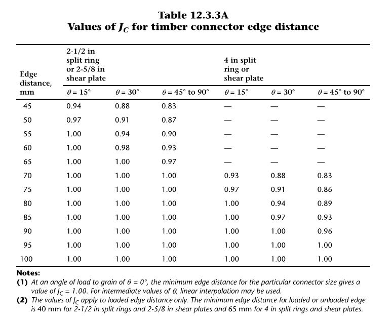
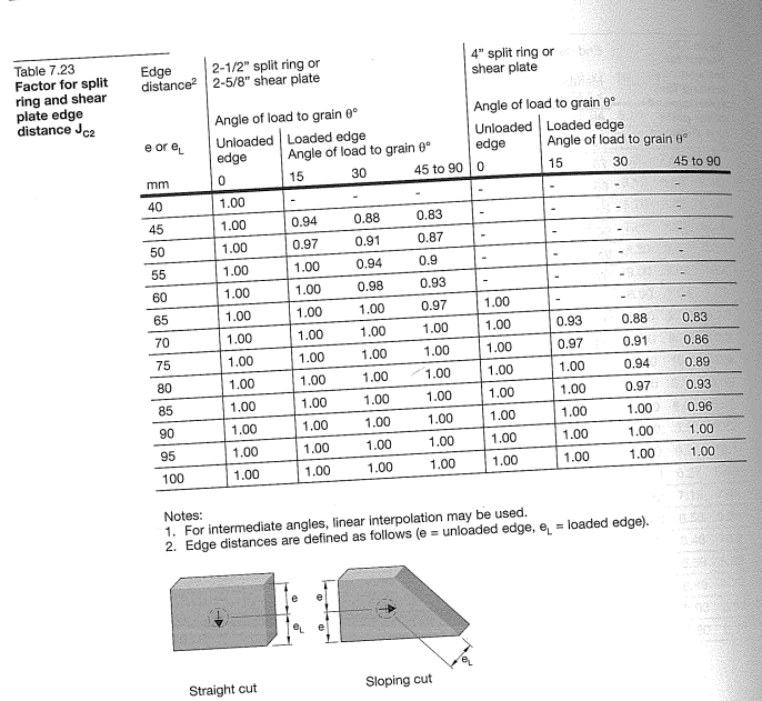
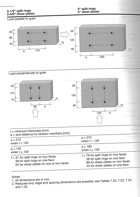
In CSA O86, the "J" factors for split ring capacity deal with end/edge distances. If I am looking to install a 4" split ring in a vertically nail laminated 38x140 deck face (meaning the split ring would "span" the edge of up to 3 boards). The loading will be parallel to the grain (along the board length). What would you suggest for a value of Jc2? I have attached a sketch on the plan view.

As always, thank you in advance.
MF
 
 https://files.engineering.com/getfile.aspx?folder=57f261e8-c7f2-41e4-bc31-aa4e0b2fe547&file=Split_Ring_Loaded_Towards_Edge.png
Replies continue below

Recommended for you

MagicFarmer:
What are you actually trying to do? You have to explain and show more than that if you want any help. I assume we are looking at the edges of a bunch of 2x6’s, or some such. And, you want to apply some sort of a concentrated load essential in the plane of the laminated panel. And, split rings will not be best for doing that, because the bolt bearing will always be the first controlling design aspect. Slit rings are particularly effective when you are trying to transfer a shearing load, btwn. two members at a faying surface. Then the bolt acts to hold the two members together at the faying surface and the split ring acts in bearing on the wood to transfer the actual load btwn. the members. For what I think you are trying to do, a shear pl. would be better. You cut a dap in the wood members to fit the shear pl. and drill a hole for the bolt. The bolt holds the shear pl. in the wood, dapped circular groove, and the shear pl. transfers the load from the bolt to the wood members, through bearing on the wood., But, I’m still not real sure what you are trying to do.
 
MagicFarmer said:
What would you suggest for a value of Jc2? I have attached a sketch on the plan view.

Great bloody question. I see what you're getting at: the rings will tend to pry apart the laminations as they push into the panel.

My gut feel is that this probably isn't much different from the monolithic case. But, then, I would like to be able to hang our hats on something more than just my own intuition.

1) Any chance the nails in tension could be shown to have a capacity comparable to the tension perpendicular to grain values of the laminations?

2) If you're close enough to an edge to be concerned, is there any way that you could get a few long SDS screws into the laminations near the connection?

This may come down to engineering judgment. It's somewhat unfortunate in that I suspect that this really is the right kind of connection for this situation. What is it that you're connecting to the panel and what levels of load are you contemplating?

 
Actually, hold the phone. The back edge of the rings should be drawing the lams together at the same time as the leading edge spreads them apart. So that's balanced and I think that your only concern is compromised capacity of the partial lam slivers at the sides of the ring. I vote for a custom Jc2 of (2 x 1.5" / 4" = 0.75). I don't think that this will be much different from the glulam case.

 
Split ring connectors neither "push" wood together nor "pull" wood apart. The spit ring fits into a grooved slot cut with a special tool into one of the members. See this video.

My uncle (structural engineer) designed numerous large wooden aircraft and blimp hangers for the military during World War II. He frequently told me that split ring connectors are the best way to make heavy-duty wood connections.
I have some old info on split ring connectors from his library on my website.

For this thread, I agree that (well constructed) nail laminated wood can be considered equivalent to monolithic wood.

[idea]
 
SRE said:
Split ring connectors neither "push" wood together nor "pull" wood apart.

Do you disagree that they do both but, hopefully, in relative net balance over a single connector? It seem pretty apparent to me, based on the geometry, that the leading edge would push the wood apart and the trailing pull it together. And nothing about the grooved slot changes that for me. For hyperbole, just imagine the thing shaped like a diamond rather than a circle.

 
MagicFarmer:
I do not have the CSA 086 code or text which you are looking at, so I don’t know exactly how to interpret your "J" factors, but I do have the following thoughts. The capacity of a split ring will be adversely affected by a very small edge or end distance. Split rings have been around and successfully used for a long time now, both in solid lumber/timber and in GluLam members. I have no trouble imagining the condition of some induced tension perpendicular to the grain, caused by the bearing forces btwn. the split ring and the wood, as KootK suggests, and that will be more critical near a free end or edge on the wood. This is particularly true when the surrounding wood can not support the forces, shear, bearing and tension, from the split ring, in the area where the outer surface of the split ring is bearing. The properly cut dap (circular groove) for the split ring causes a tight fit when the split ring is pressed into it, so it is not like the split ring is flopping around in the groove as it is loaded and distorts. But, their successful use and testing over the years has set their design values and any adjustment factors. I do not recall reading anything which indicates that Koot’s phenomenon is a particular problem as long as one pays some attention to min. edge and end distances, and proper fit of the split rings.
 
SRE said:
KootK - If you watch the video I linked to you may change your mind.

I watched it prior to my previous post SRE. I wouldn't ever be so impolite as to request a clarification from you without having digesting all of the information that you presented previously.

Alas, though, all I see in the video is that these things are steel rings inserted into routed slots. None of that changes my opinion of the state of stress which is shown below. Fundamentally, I see a split ring as being a version of a dowel fastener. And, like all dowel fasteners, it induces lateral stresses in the parent material when loaded laterally. Owing to the fact that split rings are annular rather than solid, you accrue the nice benefit that the net lateral stress integrated over the entire connection is zero. Well, it's surely not exactly zero but good enough.

c02_g9szwg.jpg
 
dhengr said:
I do not have the CSA 086 code or text which you are looking at, so I don’t know exactly how to interpret your "J" factors

For your viewing pleasure. Just as you're thinking: Canadian edge distance factors.

c01_hjsvzh.jpg
 
My first post still stands. This looks like an inappropriate use of a split ring. It appears that the load is applied through the bolt which will act like a normal dowel, and the bolt in bending or bearing on the wood will be the controlling design condition. The split ring will really transmit no meaningful load in this case, it just isn’t loaded unless the various wood plys are not fixed together in any way, so they can slip w.r.t. each other.
 
My apologies for the late response, notifications for this thread were hitting my spam folder.

@dhengr, you're right, I did not offer a great detail, please see attached for greater context.

@KootK... always with a killer detailed response, thank you. Because the deck is very long, the combination of the nail capacity and the fact that, in order to pry apart, the adjacent board would have to crush, I suspect that the laminated deck is extremely close to acting as a monolithic slab, if not just as good. I like your idea of adding SDS screws, except i believe they would interfere with the constructability. Is it possible to over-drive them so that the head is buried, as not to interfere with the lamination of the adjacent ply? I would want to have to have the contractor touch up hundreds of counter sinking holes with on-site preservative. I'm leaning towards using Jc2 = 1.00, because prying or splitting seems so unlikely... perhaps 0.90 as a "sleep at night factor."

@SlideRuleEra, thank you for the information.

@dhenger, my interpretation was that, after initial slip, that the whole point of the slip ring was better distribute the shear force over a greater bearing area. Perhaps your second point comes down to my initially poor sketch. Again, please see attached for greater detail.

I will also attached clips of the relevant pages to the Jc question below.
 
 https://files.engineering.com/getfile.aspx?folder=786a7ffd-e8e6-4190-95c7-b112b76cb52e&file=Curb_Detail.jpg
SRE said:
KootK - Ok, the video is more about the tool than the connector. Producer must have assumed that viewers know that a split ring connector is really split, not truly annular

In your mind, is the split eliminating the potential for the development of lateral stresses somehow? As I see it:

1) There would be some of this effect but not much since, even split, the ring's going to be pretty stiff compared to the wood.

2) The reduction in lateral stresses would be very much dependent on where the split winds up being relative to the orientation of the load. A split aligned with the load might do something but I'd think that a split located on the sides would do next to nothing to alleviate lateral stresses.

 
MagicFarmer said:
Is it possible to over-drive them so that the head is buried, as not to interfere with the lamination of the adjacent ply?

I don't know the answer to that but I think that it would be worth looking into. I hadn't realized that this was a new build deck. Given that it seems to be, I'm liking the local screws that much better if it's possible.

MF said:
I'm leaning towards using Jc2 = 1.00, because prying or splitting seems so unlikely... perhaps 0.90 as a "sleep at night factor."

This thread got me to thinking that I'm not entirely sure that I know the reasoning for edge distances in the first place. I'd always assumed that it was about the tendency for lateral spread in dowel fasteners (as I mentioned, I don't feel this is an issue with split rings). On the other hand, perhaps some of the edge distance logic is really about the viability of the initial installation. You know, not blowing out the wood etc. In this one respect, your NLT may not be as good as monolithic or even GLT. If your ring groove is grouted with, say, 1/2" overhanging a new lamination, can you expect to load that lamination or will that sliver of wood within the ring just disintegrate on you? This is why I recommended an edge factor assuming that you might only be able to reasonably load the equivalent of two solid laminations (3"). This is complicated, somewhat, by the fact that the original capacities surely factored in the effect that the wood nearer the center of the ring is surely the most effective at resisting load. Unfortunately, I'm not privy to any of the details of this. I put some effort into it but was unable to locate any published diagrams showing the wood stresses that one could expect within a split ring connection.

HELP! I'd like your help with a thread that I was forced to move to the business issues section where it will surely be seen by next to nobody that matters to me:
 
MagicFarmer:
Much better detail, some dimensions would have helped. I assume the curb member is an 8x8 timber, and that this is the deck of a bridge. The wear surface (full thk. 2x6’s?, or 3x) doesn’t do you much good beyond or under the curb. Why not eliminate 2 or 3 planks wide at each curb, and their fastenings, etc., and just make the pedestal an 8x8? This would save you three split rings at each of these details which I assume occur every 8 or 10’. You are using the split rings properly now that we see the details. They are transferring the load btwn. wood pieces, through the split rings, in bearing, as Koot’s sketch of 29JUL19, 00:08 shows, not through the bolt as your original sketch seemed to show. Actually, you might eliminate 3 more split rings if you could justify routing a .5-75” deep pocket for the pedestals, in the lam. deck. This would be about 7.5” wide by about 42” long, and the pedestal forces would be transferred directing to the lam. deck in bearing and shear by the pedestal pieces.
 
Status
Not open for further replies.
Back
Top