Continue to Site

Eng-Tips is the largest engineering community on the Internet

Intelligent Work Forums for Engineering Professionals

  • Congratulations KootK on being selected by the Eng-Tips community for having the most helpful posts in the forums last week. Way to Go!

Using two contact points in moving load analysis causes problem

Status
Not open for further replies.

Matte StrEng

Civil/Environmental
Feb 17, 2022
15
Hi! I perform moving load analysis using Sprung mass (SDOF system) for bridge modal identification (called drive-by monitoring) from the vehicle responses. I face a problem when using more than one contact point (like two quarter cars).

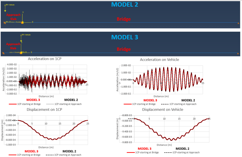
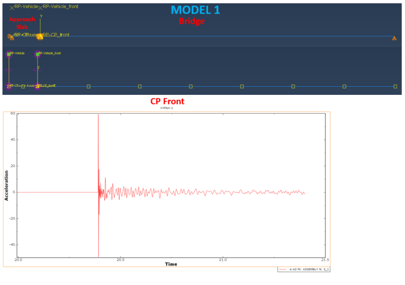
The bridge (25m) and the approach slab (2m) are modelled with a 2D Bernoulli beam element. When one Contact Point representing a sprung mass system at 5m/s is used in Model 2 and Model 3 (see Picture 2), regardless of whether the sprung mass enters the bridge coming from the approach slab or starts moving at the bridge support, both results are very coherent. It is only observed that there is a slight difference between the acceleration responses. The higher acceleration of the sprung mass in Model 2 can be due to the impact of the Contact point that comes from the rigid platform to the bridge. The jump in the acceleration when entering the bridge is reasonable and does not affect the accuracy of the results. However, when two sprung mass systems are used in Model 1 (see Picture1) (despite having the same properties as models 2 and 3), an acceleration peak (60 m/s2) occurs when the back contact point is about to enter the bridge. This occasion twists all the results. Moreover, in Model 1, I also tried to use the back sprung system (in the approach slab) without mass and force, then the same acceleration peak occurred. Using finer mesh does not solve the issue as well.

What can be the solution to this problem?
Picture1_ggyesm.png
Picture2_bhwrb4.png
 
Replies continue below

Recommended for you

How did you model that sprung mass system ? What are its components ? Which type of step do you use and what settings for contact ?

It would be best if you could share the input file for Model 1.
 
Thank you for your interest. I gave some details regarding the model below. The thing that I cannot understand is why using two contacts does not work even if all the features are the same with Models 2 and 3 that work perfectly.

1)The mass of 1000 kg assigned to each XRP- vehicle that is connected to the corresponding XRP-contact by spring-dash point element with a spring stiffness and a dashpot coefficient (axis: follow line of action selected). A 9810 N force is assigned to each XRP-Vehicle instead of gravity analysis.
2)Kinematic coupling is used as a constraint type between XRP-vehicle and XRP-contact, constraining the degree of freedom U1.
3)Surface to Surface contact interaction is applied between the master surface (the bridge’s top) and the slave surface (each contact point). By the way, both discretization method yields the same result. Slave adjustment is selected as No adjustment. Left the others as default. Contact interaction property is adopted as Frictionless in moving load analysis. Tangential Behaviour is Hard contact, and the constraint enforcement method is Default.
4)Three steps are used. First Step-static (1 sec) enables the system to reach static equilibrium. Second Dynamic Implicit (19 sec) where the cars do not move. That helps the sprung mass be completely stationary. Third, Dynamic Implicit where the sprung mass systems are moving thanks to their boundary condition V1:5 m/s separately. In Dynamic Implicit analyses, moderate dissipation is applied.

The link to the input file:
 
Here are a few thoughts after seeing your model and its description:
- I would try with more elements and with quadratic beam elements for the bridge and the approach slab
- testing other application modes in dynamic implicit step might be a good idea, maybe even a different type of step could be used
- there's also a join+rotation connector between the bridge and the approach slab - this connection may have some impact on the results when the sprung mass system passes it - perhaps a different form of connection could be tested
- it seems that the top reference points don't follow the bottom ones but move in the opposite direction - is it supposed to work like that ? Shouldn't the whole sprung mass system move along the bridge ?
 
Firstly thank you for your feedback and valuable comments. @FEAway

4) I am starting with your last comment. You are correct that the top Reference point goes in the opposite direction. I saw it in the results of U2 displacement. In the model, I actually coupled each top (vehicle) and bottom (contact point) reference point by the kinematic coupling constraining U1 to let them move together because of the boundary conditions of the bottom RP as control points (V1=5 m/s). Could you tell me first how you recognized it? So I can also check before starting an analysis. Then, what do you think about why they are not going together in these settings?

Later, I removed coupling constraints between the top and bottom reference points to simplify the model. I separately assigned boundary conditions as Velocity (5m/s in V1) to each one. So each reference points move in the horizontal direction in the way that the top one is moving together with the bottom RP. Unfortunately, I got the same wrong result as Picture 1. I am sharing the input file of this analysis.


I also tried your other suggestions as follows.

1) I tried quadratic (beam) mesh elements (B22) if you meant that; unfortunately, nothing changed. What did you mean by "trying with more elements"? If you mean finer mesh, I tried 1 cm mesh sizes, and the peak of 1.5m/s2 occurred rather than 60 m/s2 in the previous case, but the acceleration level should be around 10e-2. That's why the occurrence of such peaks twists the results.
2) The other application modes also didn't work. Did you mean I can try a different step like the Dynamic explicit step and so on?
3) I used a joint-rotation element to simulate the behaviour of a moment release available in UR1, UR2 and UR3, constrained in U1, U2, and U3. Which type of connecter as an alternative do you recommend for that behaviour? The aim is that there will be no moment transfer between the approach slab and the bridge.

Please let me know if I can try something further.
 
I realized that these RPs won’t move together since there are no constraints making the top points follow the bottom ones. You could use the equation MPC for this purpose (coupling the proper degree of freedom of these points).

Yes, I meant finer mesh. From what you said, it seems that refining the mesh can significantly improve the results - that’s a good sign. Maybe increasing the frequency of output (at least around the moment when this acceleration peak occurs) would also help.

Yes, I would check the dynamic explicit step but there you may encounter other issues with numerical noise in results.

You could try connecting the bridge and the approach slab with the equation MPC mentioned above.
 
Status
Not open for further replies.

Part and Inventory Search

Sponsor