Eng-Tips is the largest engineering community on the Internet

Intelligent Work Forums for Engineering Professionals

Utility Generator Export Issue(Imbalance) 4

Status
Not open for further replies.

Energyfit24381

Electrical
Jan 5, 2024
27
0
0
US
Hey all,

Trying to export to the grid through a step up transfer but gens are tripping on a kVar imbalance. I believe there isIs anyone aware of any equipment i can install at the generator to minimize or eliminate phase imbalance?
 
Replies continue below

Recommended for you

Is the generator looking at the delta?
Is the wye on the high voltage side and is the wye point solidly grounded?
Can you high resistance ground the wye point?

--------------------
Ohm's law
Not just a good idea;
It's the LAW!
 
Are you a long way from the substation?
Long rural lines with mostly single phase loads get worse for balance the farther out you are.
If there are voltage regulators on the line, it gets worse.
You may have equal line to neutral voltages but unequal line to line voltages and unequal phase angles, but till have equal line to neutral voltages.
If your delta side is the low voltage side, does the transformer run hotter than reasonable for the load?


--------------------
Ohm's law
Not just a good idea;
It's the LAW!
 
@jghrist its a phase imbalance that occurs when synching to the grid for export.

@waross the generator is looking at the wye side. From the drawing it does not show solid ground and also the Xfrm is at 5% impedance in lieu of the recommeded 6% per IEC 60076-5. Also, yes we are a long distance from the substation as well. Upon reading more of the report today i did confirm that the line to neutral voltages are equal and the Line to Line readings are the ones that are imbalanced.

“If my critics seen me walk on water they would say its because i cant swim”

- M.T.-
 
Energyfit24381, Excess VArs (lag) are VArs going towards Leading etc. at the generator end can all be addressed by changing the step-up transformer tap position.
If you want go towards lag, change the tap towards 1 and if the intention is to reduce Lagging VAr flow from generator, take the transformer tap away from 1.
Excess lagging VArs drawal from generator causes generator overheating and Leading VArs makes generator field weak and thus less stable.

R Raghunath
 
A suggestion as to why the grid phases are unbalanced:
On a wye distribution system, single phase loads are often connected line to neutral.
To start, imagine the four points representing a balance system line voltages and neutral point.
Now put a load on one phase to neutral.
The voltage drop will shorten that vector.
When the voltage drops on one phase, it causes the neutral point to shift.
When the neutral point shifts, the angles of the two high phases shift.
Depending on the impedance of the neutral conductor (Number and spacing of multiple ground connections and the impedance of the ground connections) there may be a voltage drop on the neutral conductor.
A voltage drop on the neutral conductor makes the shift of the neutral point worse.
Now we come to remote voltage regulators.
On long rural lines, voltage regulators are common.
These are typically connected line to neutral.
This is good for the single phase loads that are causing the issue, but makes the issue worse for the three phase loads.

On the other side, a number of machines generate a balanced three phase back EMF.
Induction motor, synchronous motors, induction generators, synchronous generators.

So we have a symmetrical back EMF or generated EMF connected to an asymmetrical line supply.
The produced EMF works to correct the line conditions.
The output of the generator will be degraded and the condition of the grid supply will be improved.
How much?
That depends on the impedance of the generator compared to the impedance of the grid as seen by the generator.
As I said; "It depends".

With a wye delta transformer, the delta must close on itself. If the wye primary is unbalanced, the delta won't close.
But it is bolted closed.
The difference between the bolted condition and the true condition (as may be seen if the delta is broken at one corner) causes circulating currents to flow in the delta.

The delta current will be three times the transformer as seen at the delta winding.

The best solution may be to add small voltages to the individual lines out of the generator so as to correct the phase and voltage balances before the generator sees them.

Let me think about this.

So with a 3% imp. transformer a 9% unbalance will cause full rated current to circulate in the delta without any usefull load on the transformer.

If your primary wye is ungrounded, then grounding/connecting the the wye point to neutral will shift much of the grid unbalance from the generator to the transformer.
Be warned that this will reduce the available capacity of the transformer and may even overload the transformer without the generator being connected.


--------------------
Ohm's law
Not just a good idea;
It's the LAW!
 
I helped with a distribution issue on a rural distribution circuit where a customer couldn’t run their 480V pumps due to phase imbalance. The phase to ground voltages were fine but the phase to phase voltages were way off. It turned out because of the heavy loading on C phase the voltage angle was significantly different, which caused the Phase-Phase imbalance.
The company was able to balance the load and correct the problem.
Your case is beginning to sound similar. If that’s true and it’s a phase angle problem, I would think that would be very challenging to solve locally. The two reasonable options would be to have the utility balance the circuit or increase your negative sequence relay setpoint and hope for the best. Short of a single phase phase shifting transformer I am not sure what other methods would work - most other voltage correction methods are attempting to adjust magnitudes, which probably would not help in this case if the problem is due to a phase angle shift. Maybe a grounding bank could be added on the primary to help the system voltages, but that comes with a host of issues to consider. Perhaps you could get really crazy and add unequal series reactances to the generator leads so the load of the machine will help correct the phase imbalance. I’ll be curious on what you find.
 
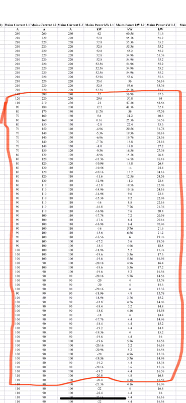
Just want to start off by thanking everyone for chiming in on this. I was able to gather some additional data today and found that voltages are stable line to line and line to neutral on all (3) phases when the issue occurs. However current, kW, and kVar are irratic. Ive attached some screen shots as well. I didnt bother with screen shotting the voltage as it was stable over the entire event.

IMG_2497_wxrent.jpg
IMG_2496_z6wmqt.jpg


“If my critics seen me walk on water they would say its because i cant swim”

- M.T.-
 
What are the line to line voltages like when the generator is not connected?
The voltages are stable because the generator is correcting the grid voltages.

Thinking outside the box, you may be able to add or subtract voltage voltage from each phase of the generator.
I hope that someone else will chime in and run the numbers to see if this will generate enough correction to be useful.
I would try a high current CT and energize the 5 Amp winding.
By forcing a current through the 5A winding the CT will become a transformer in series with the generator and by controlling the excitation current, the direction and magnitude of the correction voltage may be controlled.
To correct voltage, excite from the same phase.
To correct phase angles, excite from a different phase.
By using a 200-5 Amp or 2500-5 Amp CT you may be able to wind three turns of generator lead around the CT.
Exciting with a Variac will allow you to control the amount of bias added.
Someone younger than me, what do the numbers look like?

--------------------
Ohm's law
Not just a good idea;
It's the LAW!
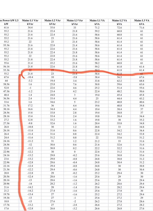
 
Line to Line voltages are not blinking at all. They stay steady at 480 +\- 2 to 3 volts.

@wcasey it really does look that way but voltage is steady.

“If my critics seen me walk on water they would say its because i cant swim”

- M.T.-
 
One thought: You might check your secondary CT circuits (if so equipped) if the voltages look solid. We’ve had strange behavior at two generating stations when CT connections get loose. We actually tripped a 100MW steam turbine on negative sequence (then the operators reset and kept trying!) and it ended up being a CT terminal was loose and was burning up.
Had a similar event on a 25 MW hydro when a terminal on a test switch loosened up and started failing and tripped the unit off.
As an aside, one time we had a CT circuit break inside a H2 cooled gas turbine generator and tripped the unit on differential. Fortunately H2 doesn’t blow up when you are above that 77% upper explosive limit as it was throwing an arc that was at 3/4” long.
It’s one more thing to check anyway.


Line to Line voltages are not blinking at all.
THAT IS BECAUSE THE GENERATOR IS CORRECTING THE VOLTAGES.
CHECK THE GRID VOLTAGES WITH THE GENERATOR OFF-LINE.

--------------------
Ohm's law
Not just a good idea;
It's the LAW!
 
@waross i was FINALLY able to do a trend on the primary while the generator is not running and the voltage is erractic. Just over the last month its fluctuated 16V with lowest at 474 and highesr at 490. They are doing alot of switching on this line

“If my critics seen me walk on water they would say its because i cant swim”

- M.T.-
 
I suspect that when the generator is online, that it will be correcting the voltages with reactive currents.
The reactive currents will cause a voltage drop in the line back to where the unbalance originates.
Probably a fairy large single phase load.
Or
Three phase loads fed from open delta banks.
The cause of the unbalance may be between you and the su, or further down the distribution line, past you.
I saw a sawmill with severe voltage unbalance issues and the resulting motor overheating.
The problem was caused by a dairy about 15 or 20 miles past us that was fed by an open delta transformer bank.
Anything that leads to a current on the primary neutral may cause voltage and phase unbalance.
The amount of voltage unbalance will be related to the voltage drop on the neutral conductor caused by the neutral current.

--------------------
Ohm's law
Not just a good idea;
It's the LAW!
 
I assume you are only looking at 1 phase? Do you have a comparison of the 3 phases magnitudes?

16V is only 3%. Utilities in the US are generally allowed to provide voltage in the range of plus or minus 5%, with a variation of up to 8%. (I think this is in ANSI C84.1 if I remember right, and it’s also in my state’s administrative code) So a 3% variation seems pretty normal.


Casey, I understood that the voltage variation was from the nominal voltage but that the phase to phase voltage should be equal.
The old rule of thumbs suggests that 3% difference in phase voltages leads to a 9% increase in motor current.
That increase in current is mostly circulating current in the rotor and motor windings and is mostly reactive.
Rant:
It doesn't seem fair that a utility is allowed to charge a power factor penalty for a poor power factor that they have caused.

--------------------
Ohm's law
Not just a good idea;
It's the LAW!
 
In the US, as you probably know, whether the utility charges for VARs depends on the utility and the state approved tariffs. My utility charges only certain commercial customers for VARs, and it’s such a tiny charge, I think a half cent per kvar, that it’s basically nothing. They used to charge for VARs from large generators but when those VAR charges indirectly contributed to the California blackouts in 1996 and 1997 they stopped doing it.
Our utility requires distributed connected generators to be in VAR or power factor mode, mostly to help prevent unintentional islands, but it also has the side effect of preventing the machine from responding with VARs to changing voltages.

That 3% imbalance you mention is the recommended maximum imbalance on utility systems in ANSI C84.1, but you probably knew that already.

Casey
 
Thanks guys, @Casey i only pulled a small sample size for about a month and all three phases have the same characteristics. When trended the primary voltage with no gen connected resembles a richter scale or a polygraph of me saying i like my wifes meatloaf. In this particular case the utility has admitted that there is an issue and we are planning to study the system to find and fix the culprit.

@waross we suspect the issue is further down stream as you mention. We will continue to investigate but your scenario above looks very similar to what we are dealing with.

“If my critics seen me walk on water they would say its because i cant swim”

- M.T.-
 
The utility probably won't go for it, but a grounded wye/delta transformer floating on the line will go a long way towards correcting the issue.
The delta voltage is unimportant.The delta transfers power and VARs between the phases and does a lot to balance the voltages and correct the phase angles.
Anecdote alert:
A customer had a wye/delta service at the end of a three phase distribution line.
The line continued for a number of miles past that point as two phases only.
Lots of loads connected line to neutral.
One of the utility engineers told me that that circuit always seemed well balanced on the substation meters.
He became aware that the customer had ceased operations and moved out and that there was no load connected to the wye/delta bank.
He issued orders that the transformer bank be disconnected.
He told me that after the wye/delta bank was taken off-line the substation meters for that circuit were all over the place.
The nice balance disappeared.

--------------------
Ohm's law
Not just a good idea;
It's the LAW!
 
Status
Not open for further replies.
Back
Top