Continue to Site

Eng-Tips is the largest engineering community on the Internet

Intelligent Work Forums for Engineering Professionals

  • Congratulations waross on being selected by the Eng-Tips community for having the most helpful posts in the forums last week. Way to Go!

Utility Power Factors over the years 1

Status
Not open for further replies.

kartracer087

Electrical
Apr 18, 2020
61
Kind of an open question, but have power factors been on the rise in general in terms of the actual connected loads? I am seeing more and more utilities removing capacitors from their system which leads me to believe it is possible that the substation load power factors have been improving in recent years. Would you say this is a fair assessment? I mean, in particular, substations feeding residential and commercial loads, not industrial.

 
Replies continue below

Recommended for you

Removing caps where? Removing them from substations while installing them out on the feeder?

I’ll see your silver lining and raise you two black clouds. - Protection Operations
 
While big motors are probably diminishing and hence the displacement power factor would be improving I'd expect non-linear loads to multiplying like mosquitoes causing an increase in the distortion power factor.

Keith Cress
kcress -
 
I think that larger users may be discovering the economies of local power factor correction.
Historically, in too many places, the accounts payable departments just pay the power invoice without reading or understanding the itemized PF penalties or realizing that the penalties are avoidable.


Bill
--------------------
Ohm's law
Not just a good idea;
It's the LAW!
 
I have been wondering the same thing. Although putting motors behind a VFD likely improves power factor, there is also a trend away from pure resistance loads. Here are the displacement power factor trends I have been pondering:
+ DOL motors with new VFDs that have filters and/or active front ends
? DOL motors with new VFDs passive front ends
- incandescent lighting replaced with CLFs
? incandescent lighting replaced with LEDs
? fluorescent/metal halide/MV lights replaced with LEDs
? Changing mix of HVAC:
+ cheap air conditioners with DOL motors being replaced with VFD air conditioners
- more houses with air conditioning (historically my area had very little AC)
- swapping electric resistance heating for heat pumps​
? Electric Vehicle charging loads. Anyone know a typical power factor for EV chargers? I would guess EV chargers would lower our winter power factor since we have a lot of resistance heating. EV chargers might improve the summer power factor.
+ Converting medium voltage distribution from overhead to underground add a small amount of distributed capacitance. On purely underground feeders, we sometimes have leading power factor at light loads just due to the cable capacitance.
- Older solar generation that only supplied real power, causing lower power factor. I am not sure how if the would change the need for distribution capacitors.
? Newer solar generation. At modest penetration levels, I assume inverter that actively control voltage should reduce the needs for capacitors on the distribution system.
- Lower loss transformer core steel. Lower real power losses in the core steel without a corresponding reduction in reactive power would lower power factor.
? Low voltage DC magnetic power supplies (i.e. wall warts) being swapped for switched mode versions

Many years ago I had heard that Europe had much stricter regulation that the USA on PQ/PF produced by end use devices. Is that true? Or does it even matter? Seems like most of the devices I buy in the USA now come with universal power supplies with a CE stamp.
 
Due to lower loss steel,no-load power factor in transformer increased-most of the cases 0.8-0.9. This is because of the reduction in exciting current with better steel. This was much more than the reduction in losses. Transformers during full load, ‘ consumes’ reactive power and to that extent helps in improving power factor.
 
Mostly residential here.
Installed or installing a total of four new banks system wide this year.
Where do you see them being taken down? I haven’t heard of any utilities around me on east coast removing them, although I only hear from about 6-8 in general conversations or at classes or seminars.
Moving them is different than removing them.
 
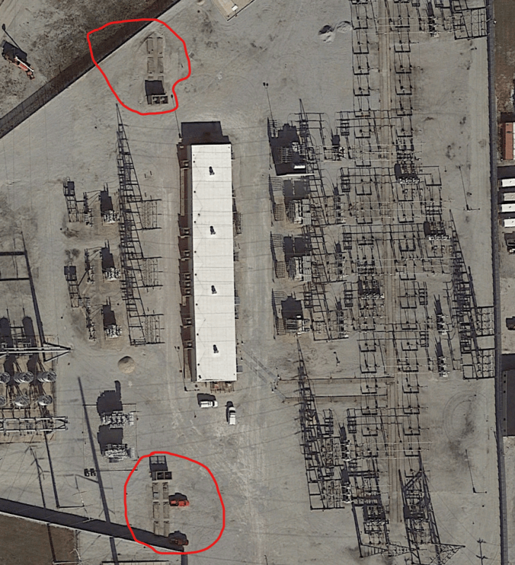
I was referring mainly to the capacitors at the station. My local Utility ComEd here in Chicago has been removing station capacitors from a number of their distribution substations. In general, I don't think they have added more capacitors in the field to their system, but they did have quite a number.

In this example, Calumet Substation, it is probably the largest distribution substation on the system. There are (4) 75MVA transformers 138-13.2kV (12.47kV system voltage). As you can see in the photo, they originally built the substation with (8) metal enclosed capacitor banks. Now they have removed all of those metal enclosed capacitor banks. I doubt they have moved this equipment inside the control house.. A quick look at the area, it looks like nearly every feeder has a capacitor bank associated with it, and I'm guessing they are each 600-1200kVAR on each bank. It is possible that their regulation has become more satisfactory due to a stiffer transmission grid which has been helped about 15 years ago by some projects that added 345kV system capacity to the area. Usually design wise you have to account for minimum voltage being 5% under nominal on the transmission side and still try and keep substation bus voltage at 100% nominal, in this case, a little over 12.5kV. This is also considering you lost a transformer and so one section of bus must carry a little more than the rated nameplate load of a transformer. I just found it interesting that in many of their distribution subs they have been removing metal enclosed banks, and thought it could be because the load power factors have been improving since the original designs in the 1970's.

Here is the substation in 2005
Sub_2005_srip8g.png


Here is the substation now, all metalclad banks are gone.
Sub_Now_n0zkun.png
 
Also, interestingly enough, ComEd hasn't been overly concerned about user's power factors like other utilities have. I have not seen them charge penalties for low power factors, and I'm speaking keep your pf at 85% or above, roughly. I have only seen a few sites where the power factor was below 80%. In a lot of the residential high-rises I've seen power factors stay around 90-95%. The older buildings with underloaded motors had very poor power factor.
 
I think I saw something about wanting to motorized the generator sets of decommissioned nuclear power plants. I don't think that ever happened so it's certainly not an explanation for the decrease in caps.
 
Have the tariffs and the basis for the PF penalties been changing?
In the days of electro-mechanical revenue meters, the power factor was determined by the ratio between monthly KWHrs and monthly KVARHrs
If the monthly average PF was below 0.9 then penalties kicked in.
A common method of bulk correction was to look at one or two years of power bills and add enough monthly KVARHrs to balance the KVARHr consumption in all but the worst month.
Bulk PF correction avoided all or most of the penalties, but from the point of view of the utility it was less than ideal.
Bulk correction would be "banking KVARHrs during the evenings and weekends but would be less effective when a facility was operating at full load.
At peak loads on the system, the customer's PF correction would be at the lessor monthly average, and peak loading times is when PF correction is most needed.
Today, with PF controllers being widely available, a customer may keep his displacement PF at a consistently high level.
I haven't seen recent tariffs, but I expect that with the capability of the newer electronic meters, PF penalties may be assessed based on KVAR usage in a moving window rather than a monthly average.
I expect and hope that customers are now mostly using PF correction panels to maintain a high power factor under all load conditions.
If the industrial customers are maintaining high power factors under conditions of high demand, there may be less need for utility owned capacitor banks.
Be warned that this is a WAG based on a little knowledge and a lot of experience. Comments and corrections are welcome.

Bill
--------------------
Ohm's law
Not just a good idea;
It's the LAW!
 
Well I think long story short, my guess is that the field pole-mounted capacitor banks are now providing enough VAR relief on the system to meet voltage regulation goals and the station banks were no longer needed. That coupled with the fact that a lot of the industrial loads in the area are now gone, those plants are abandoned now and basically rubble.

It seems as though the trend with utilties is towards relying more on the field pole-mounted or pad mounted banks (consider having 1 or 2 field banks per feeder circuit as required) rather than installing station banks and having fewer field banks. Station banks require more space and don't provide direct feeder VAR relief at the location of load, so all of the VARS have to flow back on the entire line to the substation which is more lossy. That's a very general statement of course, if you have field caps, whatever VAR on the station bus will find its way to the capacitors. Hypothetically you could have a line with low power factor and have field caps on the other line and some of that VAR would flow back to the other circuit's capacitors and some of the VAR comes from the regulating winding on the OLTC.

The general hope being the load VAR is absorbed by the capacitors and you are close to unity power factor at the substation so the OLTC can do its job of keeping the bus voltage within the +/- 5% of target. Targeting on the positive side being preferred considering line losses at the end you will be close to nominal voltage.

The transmission system absorbs the rest of the VARS from the station transformers and whatever they suck from the grid with the OLTC winding as well as the inductive reactance of the transformer itself. Thus, the transmission system will have some pretty big banks. One sub near me has a whole yard of cap banks connected to the tertiary winding of a 345kV-138kV transformer.

Another interesting thing to consider is that an OLTC transformer that has its regulating winding on the secondary winding must have the VARS from the grid flow through the transformer itself, i.e. the regulating power required has to pass from primary to secondary through the induction of the transformer. So that actually creates more losses and regulation that isn't as good as if the regulating winding was placed on the primary winding. Here in the US, ANSI standards have stated that the regulating winding is to be placed on the low voltage winding. I would consider deviating from that in certain cases and place the LTC winding on the primary side because that issue of the VAR loss going through the transformer will be mitigated. I think this is especially important for transformers that have higher impedance specs, commonly done on larger units to help keep short circuits within levels of typical distribution equipment (less than 8-10kA sym., typically..)
 
Any such observations will be very localized. Every utility will do things it’s own way, and there’s probably a negative correlation with what adjacent utilities do.

I’ll see your silver lining and raise you two black clouds. - Protection Operations
 
TugboatEng
Do you know of any articles, info, white papers etc ..regarding motoring decommissioned generators? Very interesting topic indeed. Grid level stuff.
Increased voltage support at a grid level? or just vars?

OT
 
Injecting VARs raises the voltage.
I have mentioned a couple of times in other threads the instance where a long transmission line feeding a city had reached capacity.
In this case the capacity was limited by the ability of the OLTCs to compensate for the voltage drop in the line.
The old diesel generating plant that had originally powered the city was recommissioned and used to inject VARs back into the transmission line to offset the reactive voltage drop in the line.
This greatly increased to capacity of the transmission line.
I haven't been back for over ten years. I don't know if the plant is still in service.
image_wlie0v.png


Bill
--------------------
Ohm's law
Not just a good idea;
It's the LAW!
 
Here is a link to an article about by making out of service generators into synchronous condensers at AES in Huntington Beach. A similar project was considered for the retired nuke plant at San Onofre (SONGS) but dealing with all the decommissioning work made it a nightmare, they did add two SynCons at the SONGS substation, and also 5 more around the area to offset the loss of SONGS


With some of the SynCon projects around here several cap banks have been either moved and decommissioned for various reasons. Not sure if other utilities are doing that, but SDG&E and SCE have both added a number of larger grid level SynCons last few years.

MikeL.
 
I have heard some of the older employees complained about the maintenance headaches of capacitors. I assume they were talking about paper insulated capacitors that regularly shorted, leaked, or did both. I got the impression the older capacitors may have been in the station to make maintenances easier. I wonder when utilities started using pole mounted capacitors? Perhaps the shift to from paper to film insulation in the capacitors increased the capacitor bank reliability such that that pole mounted capacitors became more cost effective. I have also heard discussions that older capacitors often had PCBs, so removal of substation capacitor banks may have been part of mitigating PCB contamination.

prc- Thanks for the correction that better core steel makes better power factor.

 
Back in the late 1980's I ran decoupled synchronous condensers in a retired / decommissioned thermal generating station to provide voltage / reactive support to downtown / metropolitan Toronto, particularly on hot, sticky summers days with scads of office tower air conditioning load on line.

Upsides: like today's static VAR compensators, units capable of both VAR production and absorption, but with the added benefit of spinning mass providing system inertia, improving stability, especially in conjunction with TSEC's [ transient stability excitation controllers ] and/or equivalent.

Downsides: major capital re-investment on equipment that may well not have been properly decommissioned and put into stasis, which may hide unknown problems; headaches of getting old equipment to play nicely with modern electronic run-up and synchronizing systems: attended operation by actual humans when in operation may well be an unavoidable necessity . . . and that's just for starters.

I really, really enjoyed operating them, especially run-ups and synchronizing, but I never had to deal with any of the issues above, although today I might . . .


CR

"As iron sharpens iron, so one person sharpens another." [Proverbs 27:17, NIV]
 
Pole mounting gets the capacitors closer to the source of those pesky VARs and reduces line losses and line voltage drops back to the station.

Bill
--------------------
Ohm's law
Not just a good idea;
It's the LAW!
 
Watts travel well; distances between generation and load can be significant. Vars on the other hand, don't travel well, "are we there yet" and the closer to the consumer they can be produced the better. That's why a former plant of ours could "deliver" Watts over a considerable distanced (at least in the marketing version of life), but there was no way that we could convert it to a synchronous condenser when the boiler was retired; it was in an area that already generated lots of vars (lots of EHV lines) and there was no means of moving those vars to any area with a var deficit.

I’ll see your silver lining and raise you two black clouds. - Protection Operations
 
Status
Not open for further replies.

Part and Inventory Search

Sponsor