Izicial
Mechanical
- Jan 5, 2021
- 1
Hello Everyone,
I have to design what is essentially a vacuum system that picks up the part and places it into the next machine in the line. I am pretty familiar with fluid mechanics from school, however we basically never touched vacuum systems.
I know to spec the suction cup itself I can use a simple Area of Suction Cup = Force/Pressure equation to find the force the cup needs to bare, however I have no idea how to go about selecting the orifice that goes into the cup or the size of the vacuum tube itself.
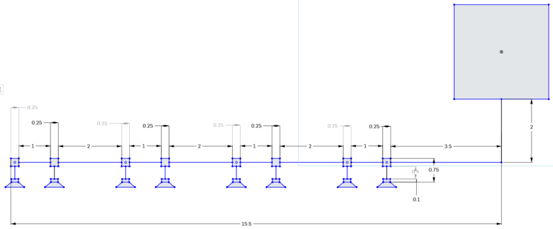
Below I have posted a picture of the setup that we will have. The large box is the vacuum generator, the straight lines are the tubes themselves, and the small squares are fittings that connect the tube sections to the suction cup assemblies.
Weight of part being lifted is 65 lbs.
The specs for the vacuum generators they have are listed here:
Operating Pressure: 6 bar
Flow Rate: 500 L/min
Any help or guidance is appreciated.
Thank you.
I have to design what is essentially a vacuum system that picks up the part and places it into the next machine in the line. I am pretty familiar with fluid mechanics from school, however we basically never touched vacuum systems.
I know to spec the suction cup itself I can use a simple Area of Suction Cup = Force/Pressure equation to find the force the cup needs to bare, however I have no idea how to go about selecting the orifice that goes into the cup or the size of the vacuum tube itself.
Below I have posted a picture of the setup that we will have. The large box is the vacuum generator, the straight lines are the tubes themselves, and the small squares are fittings that connect the tube sections to the suction cup assemblies.
Weight of part being lifted is 65 lbs.
The specs for the vacuum generators they have are listed here:
Operating Pressure: 6 bar
Flow Rate: 500 L/min
Any help or guidance is appreciated.
Thank you.