Continue to Site

Eng-Tips is the largest engineering community on the Internet

Intelligent Work Forums for Engineering Professionals

  • Congratulations KootK on being selected by the Eng-Tips community for having the most helpful posts in the forums last week. Way to Go!

Vacuum turbine is not working after rewiring 5

Status
Not open for further replies.

Viktoras

Industrial
May 12, 2023
2
Hello,

I'm using a vacuum turbine in my factory to collect dusts from several machines
factory produces kitchens. Machines are CNC nestings.
For 1,5years system was working fine. And one day the turbine motor burned.
We have rewired (local service) the motor, and it worked for 2 weeks and then the stator burned again.
we have rewired (local service) again, but this time added additional protection
* (thermo-couple and thermo-resistor)
* amperemeter to constantly measure the current in each contour (it is triangle wired for 380V)

This time Motor worked for 15min. then the protection has kicked-in


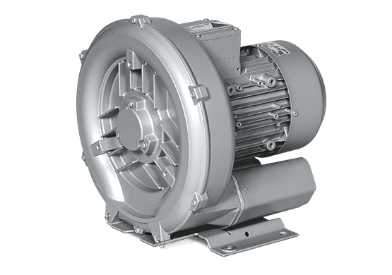
We are using Garden Denver turbine 2BH1 943-7GH37 with a 21kw Siemens motor.
-
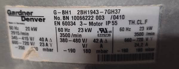
mm_fti2b4.jpg


What we know:
1. The outer system (ducts, separators, pressure valves, exhaust) has not changed
2. Before rewire it used 34-35A in each of stator contours (while turbine was integrated in system)
3. After 1st rewire it used 24-25A in each of stator contours (while turbine was integrated in system)
4. After 2nd rewire it uses 43-44A in each of stator contours (while turbine was integrated in system)
(and uses 24A while detached from the system)
5. The pressure in the system remained the same -240mbar (which is ok for this turbine)
6. Motor is wired in triangle for 380V
7. The resistance in each contour is ~0,5ohm (today)
8. The isolation is fine, the reistance is like 2Giga ohms

I suspect that the motor lost its torque after 2nd rewire

The question is - which parameters might be lost in second rewiring process, and can they be restored in 3rd rewire?

Many Thanks
 
Replies continue below

Recommended for you

Main reasons for LV motor winding failures
1. Single phasing (loss of one phase)
2. Overloading
3. Frequent starts
4. Poor quality copper (magnet wires made from impure recycled copper)

From your google photos, it looks like single phasing. And the winding (not sure original or rewound) is not a quality work.

The motor no-load current (i.e. without connecting to your vacuum system) for such high speed motors should not exceed 25% of rated current. In your case, that would be 25% of 40A = 10 Amps. If no-load current is 24 A as given by you, then the winding is wrongly done.

Muthu
 
You should consider dust buildup.
Dust may be building up in the system in a way as to affect the motor draw.
Dust may be building up on the motor and insulating it.


--------------------
Ohm's law
Not just a good idea;
It's the LAW!
 
I just looked at the fan curves for that turbine.
You probably have increased restrictions in your system.
It could be dust buildup choking off piping.
It could be plugged filters or cyclones.
It could be a change in the material which is producing the dust.
The fan curves show that the HP requirements increase as the differential pressure across the turbine increases.
Sometimes a motor burnout looks like overloading because the motor was overloaded.
Check your dust.

--------------------
Ohm's law
Not just a good idea;
It's the LAW!
 
A google search of the term;
"Gardner Denver turbine 2BH1 943-7GH37"
Will bring up several sites with downloadable .pdf files of the performance curves of the turbine.
Note: This is a turbine pump, not a centrifugal pump.
As the delta-p increases, the load on the motor increases.
This is the opposite to a centrifugal fan.
A restriction in the system will put more load on the motor.
BUT it worked for years.
What has changed?
Has the material being machined changed?
Is the material more susceptible to buildup then previously?
Has the moisture content of the material changed?
Has the RH in the factory changed? (eg; An added process that generates a lot of water vapour?)


--------------------
Ohm's law
Not just a good idea;
It's the LAW!
 
Another name for this type blower is a regenerative turbine blower.
They have a much steeper performance curve than a centrifugal blower, and as a result centrifugal blower fan laws do not apply.
Where with centrifugal blowers will have maximum power requirement with free discharge, regenerative turbines in general will have maximum power requirement with a closed discharge.
G-BH1_vq2xdg.png

2538439_bvik7n.jpg

What is the difference between regenerative and centrifugal blowers LINK?

So the inital problem may have been as waross states high differential pressure across the blower, you will need to troubleshoot this to confirm or disprove. If you have an initial setup value, it will help with troubleshooting.
However Muthu knows motors. If he thinks the rewind job is defective he is most likely correct, you need a good motor to test the exhaust system.

Before you attempt your nest restart, clean your ducts and cyclones, swabbing out with a chimney cleaners brush is sufficient. This is necessary if you operated at lower than design air flowrates for an extended time, which can result in material not being transported to the hoppers, and sticking in the ducts (reducing cross section, which increases friction head and further reduces flow rate).
The bags should be checked for blinded areas (parts of the bag with caked hardened material that does not shake off of the bags). Sometimes blinded bags can be restored by laundering them, but it is more usual to replace them.
 
Hello,

Thanks for the quick responce.

Please do not consider dust built-up in the turbine as a problem at the moment.
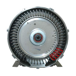
1. These photos shows what we have found inside the turbine after it has burned 2nd time. it was cleaned during rewiring process. And it remains clean now at it was not used after 2nd rewiring.
We will solve this by adding a filter between turbine and separator

2. After 2nd rewiring, the turbine was working only on test mode (it was a only a clean air circulating a system)
Also the test system was shortened - it consisted only Turbine <- Separator No1 <- Separator No2 <-air from the environment.
Separators themself do not have the filters installed. And the system worked fine for 1.5 years with the same separators. no changes were implied.

3. After 2nd rewiring, turbine could work up to 15 minutes before thermo-relay kicked-in (heat buildup due to too high amperage -44A (max is 40A))
The rewiring fault (i suspect) was detected on test system.

___________________
Regarding lamination - I have tested what is the resistance of lamination. it's like 2Giga ohms between the stator wire and a motor frame
_____________________________________
Regarding frequent start - this should not be a problem. because motor is usually working for 8hours and it's swiched off rarely, like 2-4 times in total. Now it was rewired and was a no-go from the first turn.
_____________________________________

To Edison123:
The motor no-load current (i.e. without connecting to your vacuum system) for such high-speed motors should not exceed 25% of rated current. In your case, that would be 25% of 40A = 10 Amps. If no-load current is 24 A as given by you, then the winding is wrongly done.

Could this be for a brand new motors? Our motor is like 8-10years old, so i would expect that percentage should be larger.
What we know - the vibrations of the motor is very small. (even smaller than our 12kw milling spindle which works on 24000rpm).
__________________________________

So what i understood - I should look for alternative rewiring service, which has a good reputation. and should discuss the quality of copper and lacquer which will be used. And then rewire the motor for the 3rd time.

__________________________________
 
Viktoras The lamination resistance is not measured between the stator wire and ground. It's a measure of the insulating properties of the coating on the lamination steel itself (between discrete "slices" of steel). This requires one of two specific tests: either a Franklin test (which is performed on a sample stack of laminations in a dedicated "test" setup) or a core loss test (where substantial cable is passed through the stator core to create a loop around a section of the core iron. Current is passed through the cable to create a sufficiently strong magnetic field - usually on the order of 1.3 Tesla and the temperature of the iron is measured). Ultimately, both use the energy-per-unit mass correlation to determine the efficiency of the coating. Different steel compositions will have different limits for the loss allowance.

Converting energy to motion for more than half a century
 
Viktoras

The motor no load current does not change with age, only with winding design.

Check your motor manufacturer or equipment supplier test certificate for original no-load current. It must be mentioned there.

Load current is fully dictated by load, not by motor. As waross and FacEngrPE rightly pointed out, accumulation of dust, dust type etc will overload the motor.

Add an overcurrent protection relay to your motor supply and set it to trip at 45 Amps.

When the motor overcurrent protection trips, it's time to clean your vacuum cleaner. :)

This time take the motor to a knowledgeable rewinder, who can design from scratch without even looking at the present bad winding.

If your present winder burnt the old winding to remove it, he could have damaged the stator core and a good winder will test the stator core first before doing the rewind.

Muthu
 
Status
Not open for further replies.

Part and Inventory Search

Sponsor