It is a universal problem. Easy, if you go to the text-books where all secondary effects can be disregarded, but not so easy IRL. I have had problems doing the same thing on much simpler systems. Systems where I had a DC motor coupled to the inertia to be determined. And seldom systems above ten megawatts.
The main problem in such measurements is to find and compensate for windage, non-linear friction at low speeds and such things. If there are ball bearings, it can be done. With plain bearings, not so easy.
If you can disconnect the machine from the prime mover AND have access to a drive with at least 10% of the generators rated torque, it may be done. But it is not done in an hour or two. But if you have that and can couple the drive easily to the machine, then it can be done in one very long day. Or a couple of very long Days.
Assuming Square law windage and constant bearing friction, which is reasonable above a few RPM and below a few hundred RPM, then you can run a test at different speeds to get a grip on windage. Use that to compensate actual torque when you evaluate the main test later.
The main problem is to apply an external torque. The application of an external torque to a machine requires some ingenuity, sometimes there is a free shaft available at the NDE, but mostly not. Then a belt directly on the DE shaft may be a possibility. A flat belt has worked best in my tests. A timing belt doesn't slip but there are seldom such pulleys available on the machine under test.
Then, use the drive in constant torque mode, available on DC drives and most AC drives, and run an acceleration test. Compensate for windage and bearing friction with the data obtained in the first test and calculate the inertia from net torque and acceleration.
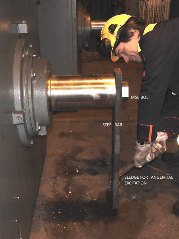
The second method is sometimes simpler and is based on the damped oscillation that a system executes when a step force is applied. Attach a lever to the shaft. That can usually be done with a clamp or using existing bolts. A clamp around the shaft is what I prefer. Then get a spring "with suitable strength and length" and affix it to the shaft and a fixed Point nearby. Stretch the spring with any suitable device and release quick so that energy is not lost by tearing the rope off. A wire cutter used to cut tug ropes may be necessary for fast release.
During this operation, record the shaft angle with a suitable transducer and calculate frequency from the damped oscillation. Once you have that, it is a standard class-room procedure to calculate inertia from the data.
I have used an inclinometer successfully to measure shaft position. It is easy to apply and produces a strong and linear signal that is easy to record with most devices. If there is low damping, high Q, the results will be as good as the spring constant measurement and length of arm measurements combined.
A Picture of a similar test (rotor resonance test) is shown in Picture below.
Gunnar Englund
--------------------------------------
Half full - Half empty? I don't mind. It's what in it that counts.