Continue to Site

Eng-Tips is the largest engineering community on the Internet

Intelligent Work Forums for Engineering Professionals

  • Congratulations SSS148 on being selected by the Eng-Tips community for having the most helpful posts in the forums last week. Way to Go!

Values for K based on End Condition

Status
Not open for further replies.

Gnique

Structural
May 9, 2016
6
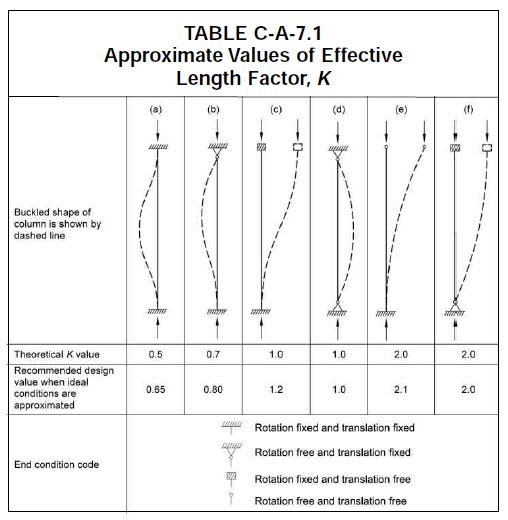
I designed a "Roof Only" Post-Frame building. The only real structural components in a roof only building are the cantilevered posts. The analyses of the posts is fairly straight forward...pretty much M=pL. My question is what does "rotation" mean in the End Condition Code when it says "Rotation Free And Translation Free" ? I ran a STAAD model of the Post / Truss / Post assembly just so I could have a value for "Rotation" computed. In the model I used an 8 x 8 DF post. STAAD returned a value for rotation of approximately 0.6 degrees. That value seemed insignificant to me so I ran the same configuration using a 2 x 4 and only got a value for "Rotation" of approximately twice (1.2 degrees) that of an 8 x 8. I have no idea how to find out the definition of "Rotation" much less how to calculate it or what constitutes a large or small value. Just to be clear, I have forever used a K value of 1.2 for roof only buildings and have always calculated sections that seem quite reasonable to me. Now if I use a K of 2.1 (Free To Rotate And Free To Translate)I begin to get what seems to me to be an unreasonably large required member section (the section went from 8 x 8 to 10 x 10). I have worked on this with two other engineers and we have gotten to the point of frustration. I honestly believe that we would get SOME closure if we could simply get our vocabulary questions answered. Thank you.
 
Replies continue below

Recommended for you

"Rotation is free" essentially means the connection at the top of the column is a pin (see table from AISC below showing graphical representations of what is meant).

If you have columns supporting each end of a truss in a conventional design, the connection between the truss and column is usually assumed to be a pin connection, so the top of the column is free to rotate and translate. This results in the cantilever column being bent in single curvature when the top is displaced sideways (case "e" in the table below).

If you provide a moment connection between the column and truss (sometimes done with knee braces), the top of the column is restrained from rotating (rotation fixed) and free to translate. This results in the cantilever column being bent in double curvature when it displaces sideways (case "c" in the table below). Also note, if using knee braces, the truss designer also needs to be aware of this and account for it in the design of the trusses - this is often overlooked in post-frame construction.
A7_cydtll.jpg
 
Similar to what dauwerda typed, you'd need the top of the column moment-connected to a stiff beam to use 1.2. It sounds like you need to use 2.1.

The rotations you mentioned for the 8x8 and 2x4 are suspect. If I'm understanding your situation correctly, the rotation should inversely proportional to the MOI. To aid in verifying what the program is doing, there's an example of how to compute this manually starting at 8:20 of
 
Status
Not open for further replies.

Part and Inventory Search

Sponsor