wokkaman
Electrical
- Sep 8, 2015
- 2
I'm pretty sure there's an easy fix but I just can't figure out how to create the PLC ladder to control three water valves, here's how it should work:
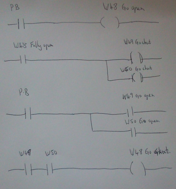
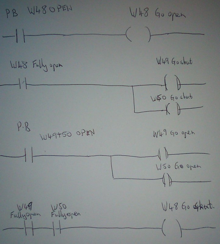
press button to select number 48 valve to go fully open (actuator's only require momentary energising to operate), as soon as it reaches fully open the fully open limit switch on number 48 valve should trigger the number 49 and 50 valve's should go fully shut. Then it's a matter of going the other way, press button to select number 49 and 50 valves to go fully open, the fully open limit switches of each valve should trigger number 1 valve should go fully shut.
Hopefully the drawing should show how I currently have the ladder logic.
The problem is that when I try to drive valve 48 open again, it's being forced closed by number 49+50 fully open limit switches as per the bottom piece of ladder.
Any ideas most welcome


