Continue to Site

Eng-Tips is the largest engineering community on the Internet

Intelligent Work Forums for Engineering Professionals

  • Congratulations KootK on being selected by the Eng-Tips community for having the most helpful posts in the forums last week. Way to Go!

Valve Selection for low pressure and low flow system

Status
Not open for further replies.

APires

Mechanical
Jan 19, 2022
3
Hello guys!
First of all, as this is my first post, a small bio: I am a 29 yo Portuguese Mec Engineer with a master's in Mechatronics living in the Netherlands. I have good knowledge in PLC programming, quite handy with workshop tools (spent 2.5 years full time as a knife maker @cruzadosblades on IG!) and helped during my teenage years repairing home appliances with my dad. One thing I know close to nothing about is plumbing, pumps and valves.

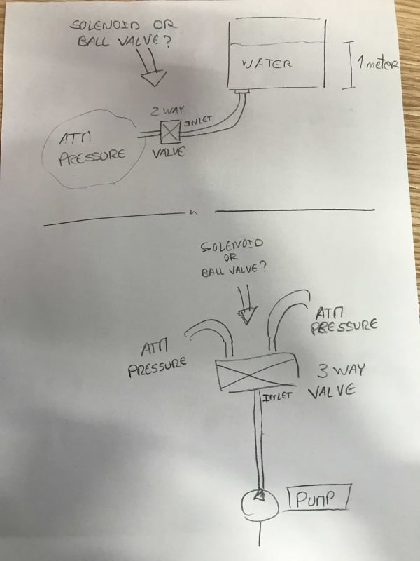
We are adapting a typical front loading washing machine to dye stuff, by mixing the intake water with ink. After wiring it up through a PLC, everything works as intended but all the batch fluid gets drained at the end with pigment to spare. Soo, as the next step, we are looking for a way to reuse it for more than once: this involves a 3/2 valve on the pump outlet, to either transport the fluid to an overhead tank that's sitting on top of the machine or to a drain pipe, but also a 2/2 valve on the bottom of the tank so that, when powered, will open and allow the fluid sitting in that overhead tank to flow back to the drum of the machine. Fairly simple to all of you, but me!

I had some spare valves that I tried but, after they didn't allow fluid passage when energized, I researched a little and found out they were indirect acting, i.e., they require dP of at least 0.2bar to fully open. I am left with semi-direct, direct solenoids or changing to a motorized ball valve.
Some extra details:
- No fast acting required
- Fluid is a solution of water and non corrosive liquid ink with no solid pigments, at a maximum temperature of 80C (about 172F)
- Pipe ID for the outlet of the gravity fed 2/2 valve is 10mm (4 inches), but for the 3/2 valve it is still undefined. I can only assume that if I get a 20mm bore valve feeding into a 10mm ID pipe, it would be overkill. Correct me if I am wrong!


So, my questions are:
1. Would a semi-direct valve work better than a direct? Are you 100% positive it would work with such low dP?
2. Would a hollow ball valve induce less pressure drop? I am using the WMachine pump (with the inneficient rectangular paddle-like impeller) which already struggles to maintain a decent flow of water for the purpose since I had to route the outlet a bit higher and these pumps aren't really known for having a high head. Solenoid valve internals typically have a higher pressure drop.

If there's something I am unaware of, please, feel absolutely free to point it out! Oh, and sorry for the long post!
Have a great day.
Cheers,
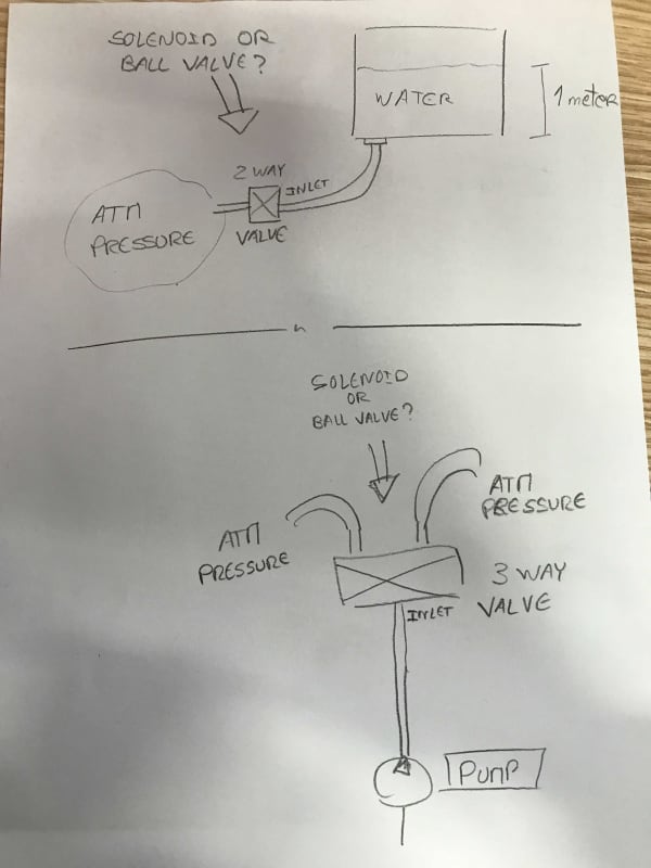
Simple_Schematic_xb2iz7.jpg
Simple_Schematic_zpt9xe.jpg

Adriano Pires.
 
Replies continue below

Recommended for you

If it was me, I would have just one tank. No pump. 4 motor operated ball valves. One ball valve isolates the tank from the machine after collecting the discharge. One valve is connected to a low pressure air supply. Another valve is connected to the inlet to the washer. Last valve is to discharge line.

The low pressure air can be used to push the discharge water with pigment back into the washer or out the discharge. Just need the air line to be at the top of the tank, and the lines back to the washer and discharge at the bottom. The valve between the washer and tank prevents the discharge from going backwards into the washer.

If you need an upper tank to ensure the amount of pigment is at a consistent level before going into the washer, it can be added into this type of set-up. Electric motor operated ball valves are inexpensive since they do not need to reverse direction. They can just keep rotating 90 degrees in one direction.
 
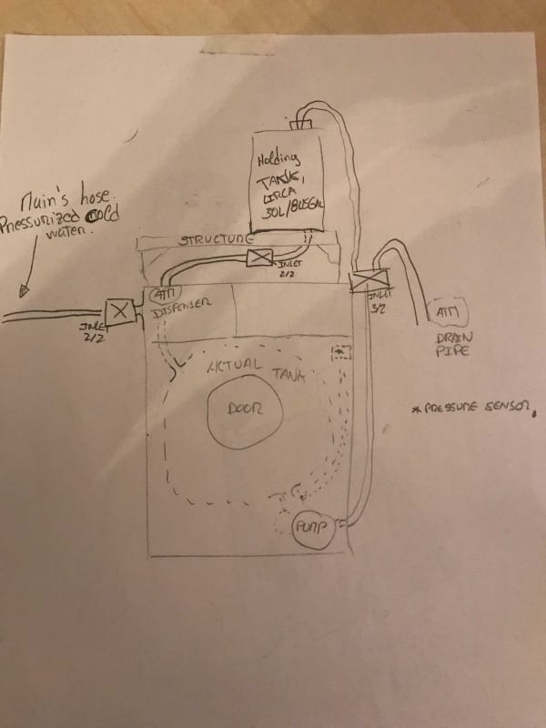
Ok, here's what. I saw your name in several threads and I am pretty sure you can help me or at least suggest me good stuff, but I am quite confused on how/what you suggested. So I will further elaborate with a fast sketch in the image below and some extra explaining.
First of all, this is merely a proof of concept for all except the electrical cabinet we already built. We intend on disassemble all the machine chassis at the end and "cannibalize" its pump (since it just makes sense(?), already on the bottom with a constant sump every time the washer has water), the outer and inner tank and door seal, indirect intake valve and some of the plumbing that is already there. The drum never rotates, so we don't even need the whole assembly of motor / pulleys / belt. We definitely also do not need the cement blocks, springs and dampers. After we see that we get good results with the setup we have, it's just a matter of making it more compact. Anyway, let's move on.

We built a small structure to accommodate the tank on top of it. For a proof of concept, easiest way of making it work that we though of was to use the pump to bring the liquid up to the tank at the end of a dye cycle, take out the dyed batch, put new ready-to-dye batch inside the washer's drum and allow the liquid to fall down, through the opening of a valve at the bottom of the tank, routing it back inside of the washer's through the dispenser. All of this automated, except the physical handling of the batches. Just for the record, the indirect solenoid valve that ONs/OFFs the intake is in its original place, working as intended.

So, as answer to my question, you definitely go for the ball valves - which is good. I believe I have easier access to synchronous motor ones that just go quarter turn from fully closed to open. One PLC output to open and one to close. Should work the same and, assuming my pump's head will be able to reach the retarded 30L tank I managed to fetch, it should in fact prove the concept x)

About your suggestion, I still struggle to understand how would you elevate the water from the washer's tank to the overhead one. Or even if the tank was sideways to it, best case scenario you could equalize it at the same height level without a pump. Not only that, but the only thing that comes to mind about using some air pressure in the tank above the water line is to either be able to keep using the initial indirect solenoid - if I managed to get a constant 0.2 bar reading, the valve would indeed work. Thing is, even after we get a system working and move on to getting it smaller and fancier, I am pretty sure it will be considerably cheaper and simpler to not use a sealed container, but instead a vented 30-50L plastic or metal tank. Fed through the top, discharged through the bottom. I don't see how I could profit in using pressurized air in this situation, but as I said above, I look up for you haha what is the physics concept I am lacking here, would you mind explaining it a bit further?

Thanks for your time, man. Much appreciated.
Best regards

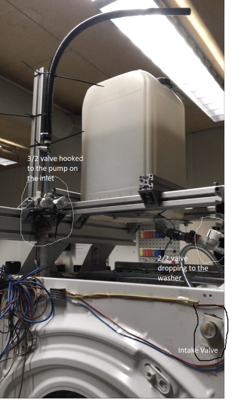
Image_from_iOS_ct3uan.jpg
 
Without knowing the pumps performance, you have no idea if it can push the liquid up to the upper holding tank. You need to know the pumps output pressure and flow to determine if it even can do this or if it will take an extraordinary amount of time.

My suggestion was to use the existing pump to move the liquid from the drain in the washer to a lower tank that is at the same level. The liquid that is in this lower tank can be pushed to an upper tank using air pressure. Figure roughly 7 bar pressure is needed to raise the fluid every 300 mm. If the line from the lower tank is at the bottom of the lower tank, then applying air pressure at the top of this tank will push the liquid up to the upper tank. With the 7 bar for every 300 mm ratio, you can figure how much air pressure is needed to push the fluid to the upper tank. So you don't need to determine a pump size. Air pressure is doing the work. You can also use the air pressure to drain the lower tank.

This is just a proposed option to avoid the pump sizing issue.
 
First of all, thanks a lot for your clear decision on the ball valve as that is what I was really looking for.
Still, and continuing the discussion, it is fairly easy to actually see how high I can get water and at what point the flow starts being annoyingly slow by climbing a ladder. Since every time I test new stuff I just use fresh water, I wouldn't even call it a mess if I underestimate the pump.

The pump is most likely the next bottleneck, but since the plumbing on the bottom is both quite good as it is, but also easy to adapt, changing the pump to something that actually I can have a data sheet of should be doable, even for me. I am not joking by saying that I would be very well served with 3meters of head and some 8 liters p min. That is a cost we can't get rid of without complicating too much the system if the stock pump doesn't work.
I am actually curious about what you said, though. We have an 8bar (116psi) compressor hooked up around the shop, ez to grab, but how would that work? None of the tanks (machine's drum and holding tank) are pressure vessels, so I don't really get it how I would manage to move the liquid around. The washer vents through the dispenser connection, and the tank vents through the lid (so that you can actually drain stuff). I am using a 25kg soap plastic jerry can with a 10cm (4") lid, which already starts to slightly buckle while full with 70-80C water, I can't really imagine asking it for much more hehe.

We bought a Siemens for €350ish, and we plan on using most of the parts/systems because it is, well, a mass manufactured item. Some 70€ for the 3/2 and 2/2 motor ball valves, pipes and thread couplings some extra 30€, some manual labor around it and you got yourself a high tech 3D Printed parts dyeing machine. Just for the record, Hewlett-Packard recommends a specific brand to dye the Nylon parts produced with MJF, their tech, sold in the high end of 5 digits. I don't doubt that it is fancier and slightly more engineered, but we had good results. It is just being able to reuse it.

Thanks for your time!
Best regards

Just for clarity, here's a closeup from the back of the machine. As you can see, all according to safe electrical wiring regulations. [bigsmile]
Backpic_dmyw8o.png
 
Status
Not open for further replies.

Part and Inventory Search

Sponsor