Continue to Site

Eng-Tips is the largest engineering community on the Internet

Intelligent Work Forums for Engineering Professionals

  • Congratulations KootK on being selected by the Eng-Tips community for having the most helpful posts in the forums last week. Way to Go!

Vapor LPG injection using Speed-Density control algorithm

Status
Not open for further replies.
Hello All. There is a vapor LPG port fuel injection. Speed-Density air mass estimation is used. However, my calculations seems to be incorrect (the calculated injector pulse width does not produce a correct mixture) and I do not know what can be wrong. I really appreciate any kind of review or double check. For example, when engine is idling:

Cylinder volume incl. combustion chamber (V): 0.388 l
Manifold air pressure (P): 40 kPa
Volumetric efficiency (VE): 0.53
Manifold air temp (Ta): 23°C (296.15 °K)
Molar mass of air (Ma): 28.97 g/mol
Gas constant: 8.314 J/°K/mol

Estimated airmass used per one working cylce (ma):
ma = (VE * P * V * Ma) / (R * Ta) = (0.53 * 40E03 * 3.88E-04 * 28.97) / (8.314 * 296.15) = 96.8 mg of air per cycle

Fuel mass (mf): (Stoichiometric AFR for LPG is 15.7)
mf = 96.8 / 15.7 = 6.16 mg

Injector specifications by the manufacturer:
Static flow (isf): 38 SLPM (Standard liter per minute, means at 0°C and 101.325 kPa), @ 1 bar differential prerssure
Offset (io): 0.79 ms @ 14 V, 1 bar diff. pressure

Conditions:
Supply voltage = 14 V
Fuel pressure = 1.4 bar (this gives a diff pressure 1.0 bar)
Fuel temperature (Tf): 50°C (323.15 °K)
Molar mass of vapor LPG (Mf) (assuming 1:1 propane:butane) = 51.11 g/mol

Calculate the required fuel (LPG vapor) volume (Vf) at 50°C and 101.325 kPa:
Vf = (mf * R * Tf) / (Mf * P) = (6.16E-03 * 8.314 * 323.15) / (51.11 * 101325) = 3.196 ml = 3.196E-03 liters

Then, calculate the required injector pulse width (IPW):
Static flow (isf): 38 SLPM = 0.6333 SLPs
IPW = Vf / isf / 60 + io = 3.196E-03 / 0.6333 + 0.79E03 = 5.836E-3 s = 5.836 ms

HOWEVER, on the real engine, I have to open the injectors for approx. 10 ms to achieve lambda = 1. I also tried to measure the dynamic behavior of the injectors and the results are almost same as the manufacturer reported. So it seems I calculated something wrong what I do not see.. Do you see that?
THANKS A LOT
 
The crux of speed density metering is knowing the volumetric efficiency - how do you know it?
I find your assumed manifold air temp questionable - at idle, it can be quite a bit warmer than ambient, due to heat transfer.
For the same reason, your assumed fuel temp may be low.

"Schiefgehen wird, was schiefgehen kann" - das Murphygesetz
 
Hi Lou Scannon, thank you for reaction. I'm aware of the uncertainty of the air or fuel temperature and the volumetric efficiency. However, the difference between the calculated and really needed fuel mass is too big. To get the fuel mass matching, I need to set the VE more than 1 or consider the intake air temperature over 300°C.. Regarding VE - I do not know the value exactly, nevertheless, the value is usually something about 0.5 at idle for most engines. I think I can not get that huge error by wrong assumptions of the temperatures or VE. It's strange for me..
 
How do you know your fuel pressure? Is it reported by a sensor, or measured by a reference gauge when you adjust the fuel pressure regulator?

"Schiefgehen wird, was schiefgehen kann" - das Murphygesetz
 
I assume you are opening the injector once per engine working cycle?

je suis charlie
 
Yes, there are a fuel pressure and temperature sensors on the injector rail. One injector pulse per cylinder working cycle. Both manifold air pressure and fuel pressure seems to measure correctly since they indicates 96.8 kPa on atmospheric pressure, which corresponds to the current altitude.
 
You have accounted for the reduced air density at idle, twice in your formula for air mass. My preference is to base VE on air density in the manifold which means VE remains the same (~100%) regardless of throttle opening.

mados650 said:
Estimated airmass used per one working cylce (ma):
ma = (VE * P * V * Ma) / (R * Ta) = (0.53 * 40E03 * 3.88E-04 * 28.97) / (8.314 * 296.15) = 96.8 mg of air per cycle


je suis charlie
 
You have accounted for the reduced air density at idle, twice in your formula for air mass
Not sure about that... The first term is the VE, which is plausible for idle of a variable speed engine, while the second term is the manifold pressure, which is also plausible for idle.
VE across the intake valve, in the definition familiar to me, is a strong function of RPM and a weak function of conditions in the cylinder, intake manifold and exhaust manifold.

"Schiefgehen wird, was schiefgehen kann" - das Murphygesetz
 
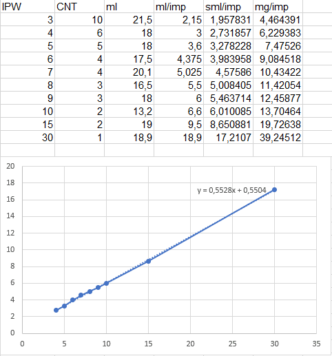
I Continued to find what's wrong.. I tested the dynamic behavior of the injector on the target system - replaced the vapor LPG supply to the injector rail by a pressurized air with a constant pressure and remove the outlet hose of one injector from the intake manifold fitting and measure the delivered air volume. So the same ECU, injector, wiring harness.. The air volume have been measured using a classical lab method - to release the air into the graduated container under the water and keeping the water level equal. Conditions were:

Absolute air pressure in the rail: 196 kPa
Barometric pressure: 96 kPa
Ambient temp: 12° C
Supply voltage of ECU: 14.0 V

Dynamic_roeezr.png


Where:
IPW = Injector pulse width
CNT = Count of the pulses
ml/imp = measured air volume per one pulse at 12° C and 96 kPa
sml = measured volume per one pulse recalculated to 0° C and 101.325 kPa // sml = (ml * (273.15/(273.15+12))*(96/101.325))

Results:
Static flow is 0.5528 SLPS (standard liter per second)
Offset is -0.5504 ms .. This is a bit strange to see a negative offset. I think it means that the open time is shorter than the close time. There is a peak&hold type injector.

However, to deliver above mentioned 3.196 sml of the gas, I need to open the injector for (3.196 - 0.5504) / 0.5528) = 4.786 ms .. Looks plausible compared to above calculated 5.836 ms, since the injector manufacturer does not specify a dynamic behavior. They specified just complete open time, complete close time and static flow. This means the above calculation does not consider that the gas flows also during opening and closing phase of the injector.

But, still don't know why my engine needs 10 ms open time under this condition. :D

Questions:
Can I make a mistake using an air instead of vapor LPG? I don't think so since I measured a volume.
Could the things change when the injection is performed not from approx. 2 bar (rail) to 1 bar (manifold), but from e.g. 1.4 bar to 0.4 bar? I don't think so since the diff pressure is the same.
 
The pressure ratio matters, but in your example not really. As long as the ratio is about 2:1 or greater, sonic flow assumptions can be used.

"Schiefgehen wird, was schiefgehen kann" - das Murphygesetz
 
Good idea. Thanks for that. Are we sure that the critical pressure is not reached? When idling, the pressure ratio is 140 kPa : 40 kPa = 3.5 : 1. I'll try to calculate tomorrow.
 
Lou Scannon said:
Not sure about that... The first term is the VE, which is plausible for idle of a variable speed engine, while the second term is the manifold pressure, which is also plausible for idle.
VE across the intake valve, in the definition familiar to me, is a strong function of RPM and a weak function of conditions in the cylinder, intake manifold and exhaust manifold.
Yes - and I personally prefer your definition of VE but the alternative definition, of airflow across the air filter, is widely used.

@mados650 How was the VE determined?

je suis charlie
 
@gruntguru: The VE for various manifold pressures and RPMs (VE table) are determined on the real engine running on the dynamometer. At the beginning, we do not know the VE since it depends on a real engine dynamic flow behavior (camshaft shapes, combustion chamber shape, intake/exhaust ports length and shapes etc..). However, we need at least partially correct values to be able to start the engine and run. For this purpose we can use the VE table for a similar engine or the initial VE table generator by Bowling @ Grippo (see the link below), which generates the initial VE table based on the engine parameters and known basics of reciprocating engines behavior. With this table the engine can start. Then, VE table is tuned on the dyno based on the actual lambda measurement. There is a typical VE for idle between 0.5 and 0.6 for all engines I have seen. But here, I have to set the VE greater than 1 for idle to get the stoichiometric AFR. This looks like there is a mistake somewhere.

You have mentioned the alternative Speed-Density algorithm which is also commonly used. Can you describe this more in detail?

 
Not an alternative speed density algorithm, simply an alternative definition of VE which compares consumption of atmospheric air to the engine displacement as opposed to the correct definition based on volumetric consumption of air at manifold conditions.

BTW, I agree critical flow conditions at the injector nozzle is the probable cause of your miscalculation.

je suis charlie
 
Hi Guys, I finally used the thermomechanics approach to solve the fluid flow through a nozzle and it gives me very accurate results. Thank you for your review and the crucial hint with a sonic flow.
 
Status
Not open for further replies.

Part and Inventory Search

Sponsor