Continue to Site

Eng-Tips is the largest engineering community on the Internet

Intelligent Work Forums for Engineering Professionals

  • Congratulations SSS148 on being selected by the Eng-Tips community for having the most helpful posts in the forums last week. Way to Go!

Venting holes when welding to sealed HSS 1

Status
Not open for further replies.

StructMB

Structural
Dec 23, 2014
9
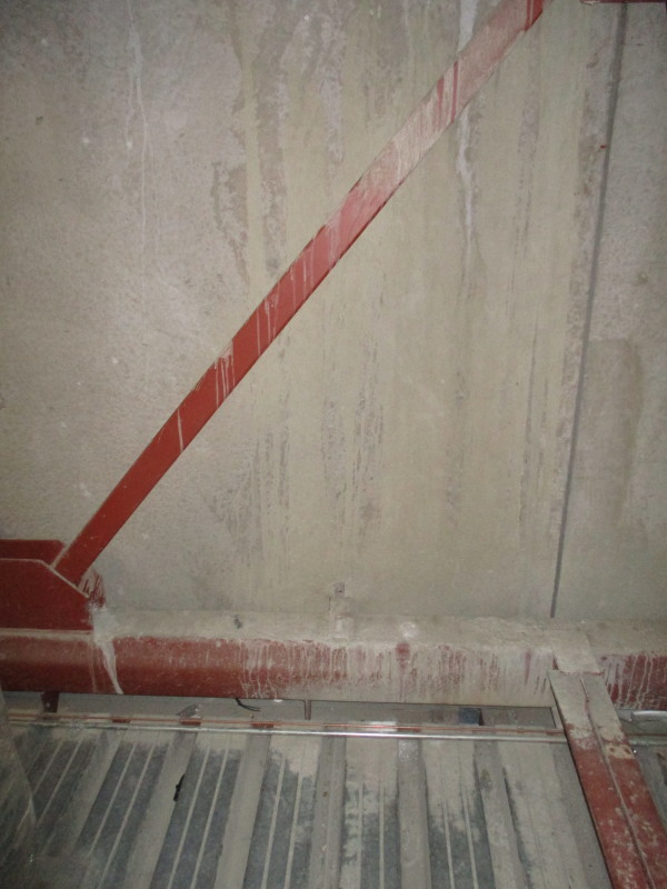
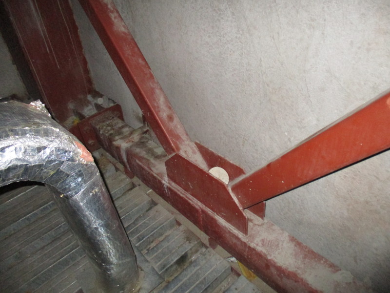
I was asked to comment on a deformation observed on a truss's bottom chord fabricated with an HSS. Indeed, the two side walls of the HSS are bulged out for approximately 3/8" for the bottom chord's entire length. It does not seem to be an overstress problem since this member is most likely under a tension load. The truss is 40' long and the damaged bottom chord was made with a HSS 8x6x1/4. I've noted that a reinforcing plate was added to this sealed hollow steel sections without the use of a venting hole. Would this field welding of a reinforcing plate (1/4" fillet weld, 6' long) be enough to increase the internal pressure in the HSS to cause this bulging of the side walls?
 
Replies continue below

Recommended for you

does this have HSS web members as well? there could have been an issue at the joints, where a web/vert was in compression on bulged the side walls. then someone went in a reinforced to truss afterwards?
 
The web members are also made with HSS. But the observed bulged is for the entire length of the bottom chord. It it is not only localized at one connection. We suspect that the plating was added on site during erections. Nevertheless, could it explain the bulging of the entire bottom chord?
IMG_0380_qvzenr.jpg

IMG_0384_wb8525.jpg
 
No way that the weld generated enough heat to raise the internal temperature of the air inside the tube so much that it bulged the entire tube along its length. Zero chance.

The bottom chord of that truss has some unexplained stresses coming from somewhere.

How close to flat/straight is the bottom chord from end to end?
 
Lessee...take a 1" wide strip across that 8" face, treat it as a simply-supported beam.
Section modulus = 1/12 x 0.25^3 x 1"/ 0.125" = 0.0104 in^3.
Stress of 46,000 psi then equates to a moment of 480 in-lbs.
Momeent = 1/8 wL^2, with L = 8" gives w = 60 lbs/inch load required.
That load is the internal gauge pressure, requires 75 psi absolute pressure. Assuming 15 psi initial pressure, with pressure proportional to absolute temperature, that gives (460 + 60) x 75/15 - 460 = 2,100 degrees F average temperature in that tube. That would amount to the entire tube glowing red- or white-hot.
Check my numbers there, but it doesn't sound like sealed tube is the issue.

If there was a lot of water trapped in there, it'd be a different issue.

Weld distortion might be a culprit.
 
To jgKRI:

The bottom chord is pretty leveled. Actually, the truss was cambered 3/8" in order to achieve a "perfect" levelness under the concrete floor self-weight. I just wanted to touch base with somebody to find out if there is enough heat generated in the welding process of this reinforcing plate that could cause such an internal pressure in the sealed HSS. I doubt it is the case, but my knowledge in welding is very limited.
 
It visually looks like web crippling to me, but I'm struggling to visualize how it could have possibly happened here.
 
To Canwesteng:
I sure look like web crippling but it is not localized under the diagonal connection. In fact the buckling is uniform for the entire length of the bottom chord making it hard to explain.
 
Do we know the HSS didn't look like that before fabrication/erection?
 
To: Lomarandil

Nobody knows when this deformation did happen. The only area where the HSS side walls are not buckled is where the reinforcing plate was added and locally at the sway trusses ("diagonal bridging") where their vertical connection plates provided enough stiffness to preventing the deformation.
 
very strange....why was the reinforcing pl added?
8x6x1/4...any type of internal press wheather from the heat generated by the weld or from freezing of any liquid inside the pipe would have to be of such an exact level such that it only affected the sides(8") and have no affect on the top & bot(6")..highly unlikely...without any further info I would go with what Lomarandil suggested that it was in that state before fabrication....
 
Could they have used a damaged tube from the get go?
 
I've got a dark horse theory but I need a little more information:

1) What's the average spacing between bottom chord panel points?

2) How tall is the truss?

3) Is the truss top chord flat or pitched?

4) What kind of section is used for the top chord and do you see any of the same phenomena there?

5) The first photo suggests that gravity load is not being delivered through the panel points. Is that generally the case?

6) Does the degree of the bowing fluctuate at all between panel points? Or is it utterly constant?

5) Any chance the bowing is greater near the supports and somewhat less near mid-span? I'm talking overall here, not between panel points.

Okay, a lot more information.


I like to debate structural engineering theory -- a lot. If I challenge you on something, know that I'm doing so because I respect your opinion enough to either change it or adopt it.
 
To kootK:

1 , 2 & 3) Bottom chord panel points at 10' c/c, Truss span = 50', Warren Flat Truss Configuration with first diagonal in tension, Truss clear height= 85", 5 panel points at truss top chord equally space at 10' c/c.

4)The top chord is the same as the bottom chord (HSS 6x4x1/4") and it does not shows signs of deformation. A bit strange since it is most likely in compression.

5)Most of the gravity loads are transferred to the top chords and they are uniformly distributed. They come from a concrete slab on deck sittings on the top chord. For the bottom chord, there is a little bit of gravity loads transferred from a "deck" that serves as a walking surface within an interstitial mechanical space. This deck is perpendicular to the bottom chord and it is supported by an continuous angle welded under the bottom chord.

6) The bulging is fairly constant with the exception of two following locations where there is no bowing:
- at the reinforcing plate;
- at the four connection plate welded perpendicular to the side of the bottom chord for connecting the sway trusses.

7) The bowing is the same for the full 50' length, therefore it appears as if it does not vary with the axial load present in that bottom chord.

How much water would it take for it to bulge in freezing conditions? If the reinforcing plate was added because of the presence of a damage such as a hole that would have allowed water infiltration within that bottom chord designed to be sealed. The bulging might be explained by the freezing of this water during the first year construction cycle (before it was protected from winter conditions).

Thank your for your comments,
 
StructMB said:
How much water would it take for it to bulge in freezing conditions

I'm relatively confident that for ice formation to cause that bulge, the HSS would need to be completely full or nearly completely full with water.
 
You have a joist (ceiling purlin?) framing into the truss at a non-panel point and that load looks to be isolated to just the visible side wall side of the bottom chord. Could this load have loaded the bottom chord so that the side wall is crushing or buckling along the length? if the same load is along length at intervals the zone of influence may have turned continuous, especially if the truss tries to heave up during load reversal or a heat cycle without adequate bearings (building heat cycle causing compression in the truss bottom chord, not from welding). If the tube was a welded tube maybe this is the weld line or a natural hinge location or maybe it is just the center or a fix/fix column?
 
Thanks for the info strucMB. Unfortunately for me, none of it really supports my hypothesis so I'm back to being empty handed.

I like to debate structural engineering theory -- a lot. If I challenge you on something, know that I'm doing so because I respect your opinion enough to either change it or adopt it.
 
The bottom chord connection to the column looks like a hard connection to me. What's on the other side of the columns? Could it be more trusses that would put the bottom of this truss in compression?

Even if there's compression in the bottom chord, it's hard to imagine that you'd get such uniform crippling without some evidence of global chord buckling. I'd also expect longitudinal crippling to be wavy along the length of the chord, not uniformly bulged out.

The concept of a chord damaged prior to erection is attractive except for thise locations where there is no bulging. They would have had to have fixed the bulging at those locations if, say, the HSS was crushed in storage or something.

I like to debate structural engineering theory -- a lot. If I challenge you on something, know that I'm doing so because I respect your opinion enough to either change it or adopt it.
 
What about moment applied to the side wall of the HSS through the flanges supporting the floor of the intermediate space?
 
If the reinforcing plate and shear tabs were shop welded on, then it was stored away laying flat and a large load was placed on top of it, that would do the trick.

The side walls would buckle in this exact pattern - everywhere except where there's extra steel.
 
Status
Not open for further replies.

Part and Inventory Search

Sponsor