Continue to Site

Eng-Tips is the largest engineering community on the Internet

Intelligent Work Forums for Engineering Professionals

  • Congratulations SSS148 on being selected by the Eng-Tips community for having the most helpful posts in the forums last week. Way to Go!

Verification of a simple preloaded bolt FEA model with analytical calculations

Status
Not open for further replies.

BioMes

Bioengineer
Nov 2, 2022
40
Hello everyone!

I'm working on a simple benchmark problem for FEA software. It involves the following simplified model of a bolted joint:

bolted_joint_model_2_knxjjo.png


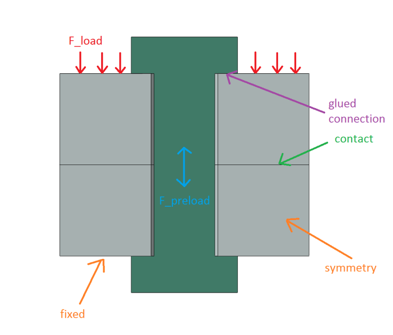
It's not a real bolt, the geometry was made up by me. For now, I only want to test the general procedure.

This FEA model represents half of the whole joint. The bolt is a single part (shank + head + nut), perfectly bonded (glued/tied) to both rings forming the joint. Pretension force F_preload = 200 N is applied to the bolt in the first step of the analysis while in the second step, pretension force is disabled and actual compressive load F_load = 400 N is applied to the top surface of the upper ring. Of course the values above are half of the load applied to the full joint. The bottom surface of the lower ring is fixed. Frictionless contact is defined between the rings. My goal for now is to obtain the force in the bolt at the end of the analysis (after preload stops working and actual compressive load is applied). From the analysis I get around 188 N (I confirmed that by running an analysis without symmetry). But the problem is that I can't get good agreement with analytical calculations. My first approach was simply superposition of the stresses (F_preload/A_bolt - F_load/A_ring) but it gave me around 171 N so I started searching for more accurate approach. I've found a nice article describing the use of a standard method known from literature (accounting for bolt and joint stiffnesses and involving equivalent cylinder to calculate the stiffness of the joint) and comparing it with FEA:
This article uses formulas from "Introduction to the Design and Behavior of Bolted Joints" by J.H. Bickford. Here are my calculations based on that (for the full model):

calc_l0boz9.png


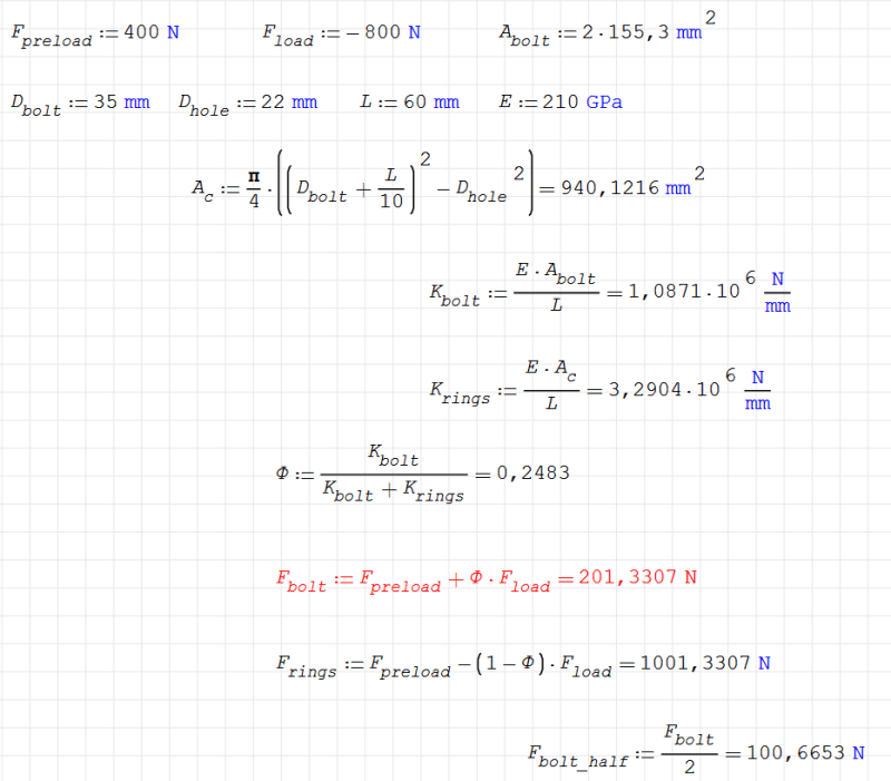
where: D_bolt - diameter of contact between bolt head and joint (it's a ring so a bit confusing to me), L - height of bolt shank/joint, D_hole - diameter of the hole in the joint, A_bolt - cross-sectional area of the bolt.

As you can see, bolt force according to this is around 201 N (100 N for model utilizing symmetry) so way too low. I thought that the problem might be caused by the fact that those equations are meant for tension, not compression but I can't get agreement for tension either. I've also tried applying F_load to the top surface of the bolt head like in the article but it didn't help. There's always such a large difference. I feel that I'm making some silly mistake somewhere here. Do you know what can be the cause of the problem? I will be really grateful for any help.
 
Replies continue below

Recommended for you

Hi

If you have a bolt preload at 200N and force applied to the joint of 400N the bolt force is automatically zero, the joint is no longer in equilibrium. If you start with a preload higher than the external force on the joint and then increase the external load then you need to do the analytical calculations step by step depending on what increments you increase the external force in.

Also if you apply a compressive force to a joint it cannot increase, in your calculation you apply -800N to the joint and then you have added the preload to obtain 1000N to the rings however if you apply - 800N to the joint then in your model it cannot increase full stop.

“Do not worry about your problems with mathematics, I assure you mine are far greater.” Albert Einstein
 
Thank you for the reply. In FEA I apply preload in the first step and the software adjusts the length of the bolt accordingly. Then the second step starts from that adjusted configuration and the force in the bolt changes due to external load applied in this step.

From what I've read in the literature, the analytical approach (involving external tensile force) also assumes that preload is applied first causing elongation of the bolt and compression of the joint. Then external tension is applied, partially unloading the joint and inducing further elongation of the bolt. Final equilibrium is considered and bolt force is calculated as F_bolt = F_preload + Φ*F_load.

If I keep the numbers (in the article preload is lower than the maximum external load) but assume tensile external force (F_load = 800 N), I get F_bolt = 598.67 N (299.33 N for half model) and F_rings = -201.33 N. In this case, from FEA I get bolt force of 399.52 N for half model so 799.04 N for full model. I wish I knew what causes that difference of almost exactly 100 N for half model and 200 N for full model.

If I also increase preload to 900 N for full model (to make it higher than the external tensile load), I get bolt force of 931.3 N from FEA and 1098.67 N from analytical calculation (both values are for full model).

Finally, if I use that higher preload but apply external tensile load to the head of the bolt (like it's done in the article) instead of the top ring, I get bolt force of 1008.61 N from FEA and same as above from the analytical approach since it doesn't account for the area of the surface to which external force is applied. The difference is almost exactly 90 N for full model this time. Those relations between the results are really strange here.
 
I'm not sure why you chose to benchmark with a bolt model ... probably the last thing I'd chose 'cause there are so many things you'll have difficulty modelling.

"Hoffen wir mal, dass alles gut geht !"
General Paulus, Nov 1942, outside Stalingrad after the launch of Operation Uranus.
 
Well, maybe I shouldn't call it benchmark because it's not meant to be used for comparison of performance of different solvers. It's just a simple example of bolted joint FEA model that I want to verify with analytical calculations. It will be used to test the preload functionality in open-source software and for educational purposes.

Interestingly, I got almost exactly 800 N for the full model in both FEA and analytical calculations when I changed the preload to 600 N and used the same external tensile load (800 N) but it doesn't make sense since bolt force is the same as external force here. For all other cases (like F_preload = 650 N) there's no agreement. I wonder what's going on here.
 
Hi Biomes

This quotation from your post I agree with.

From what I've read in the literature, the analytical approach (involving external tensile force) also assumes that preload is applied first causing elongation of the bolt and compression of the joint. Then external tension is applied, partially unloading the joint and inducing further elongation of the bolt. Final equilibrium is considered and bolt force is calculated as F_bolt = F_preload + Φ*F_load.

However that’s applies tension to the joint and you are applying compression and that’s were in my opinion your problem lies.
When a bolt is tightened onto two plates or discs we agree the bolt is elongated and the plates are compressed, at this point the compressive force on the plates equals the bolt tension force or bolt preload.
So the bolt is stretched like a tension spring and the plates compressed, therefore the bolt wants to return to its original length ie by shrinking and the compressed plates want to expand to their original thickness.
If you now apply an external compressive force to the two plates and compress them further the bolt shrinks back toward its original length and reduces its tension, further if you apply a compressive external load to the plates which equals the original bolt preload then the bolt returns to its original length and the bolt preload is zero. Once the bolt preload equals zero the only thing you are achieving is compressing to plates the bolt is doing nothing.

“Do not worry about your problems with mathematics, I assure you mine are far greater.” Albert Einstein
 
It definitely makes sense but I can modify the problem under consideration and assume external tensile force. However, for such a case I also don't get the agreement between FEA and analytical solution. In the previous posts, I described the results obtained for external tensile force. For example, if I just change the compressive force in my original case to tensile (without changing any values), I get the hand calculated bolt force of 598.67 N for the full model and thus 299.33 N for the half model which compared with FEA results (799.04 N and 399.52 N respectively) gives a difference of around 200 N for the full model and 100 N for the half model. There must be some mistake causing such a regular discrepancy.
 
Hi Biomes

I believe your mistake is trying to analyse a bolted joint with a bolt preload which is less than the external force you are applying to the connected components,bolted joints are designed to have a bolt preload higher than the external force applied to the joint, if you apply an external force which is greater than the bolt preload then the joint won’t work and that applies to a tensile or compressive external force.


“Do not worry about your problems with mathematics, I assure you mine are far greater.” Albert Einstein
 
if by "joint won't work" you mean it'll gap and become unsafe or at lest "not as per design", but the joint should hold together under tension loads less than the bolt allowable. But a gapped joint pushes lateral loads through the bolt and will I suspect behave quite differently to a nicely clamped joint.

"Hoffen wir mal, dass alles gut geht !"
General Paulus, Nov 1942, outside Stalingrad after the launch of Operation Uranus.
 
It's just a simple example of bolted joint FEA model that I want to verify with analytical calculations.

I agree with rb, if you want to create a good "beat your head against the wall" situation which will only lead to frustration, pick a bolted joint to attempt to analyze with a FEM. Its very complicated, hard to model, hard to understand the results, etc.

Also, the loading shown in your figure will not load the fastener; you show a compressive load on the upper plate which will simply be reacted by the fixed surface of the lower plate.
 
Hi rb1957

Biomes wants to calculate the bolt force after preload stops working and the compressive load to the clamped plates is applied by definition if the external force compressing the plates is greater than the bolt preload then the final bolt load will be zero.

See Biomeses quote below

Biomes said:
[his FEA model represents half of the whole joint. The bolt is a single part (shank + head + nut), perfectly bonded (glued/tied) to both rings forming the joint. Pretension force F_preload = 200 N is applied to the bolt in the first step of the analysis while in the second step, pretension force is disabled and actual compressive load F_load = 400 N is applied to the top surface of the upper ring. Of course the values above are half of the load applied to the full joint. The bottom surface of the lower ring is fixed. Frictionless contact is defined between the rings. My goal for now is to obtain the force in the bolt at the end of the analysis (after preload stops working and actual compressive load is applied). From the analysis I get around 188 N (I confirmed that by running an analysis without symmetry)]

“Do not worry about your problems with mathematics, I assure you mine are far greater.” Albert Einstein
 
Just an observation, under preload conditions the bolt tensile strain is obviously based upon the volume of the bolt shank, effective thread engagement length and a small portion of the bolt head. The nut will have an effective thread engagement length and be in compression. In the case of the compressed plates, various text will state the compression zone can vary from a cylinder, sized by the bolt head and nut or washers, conical zones emanating from the underside of the bolt head / nut, to a compressed barrel zone. When an external load is applied, what needs to be assessed is where the load actually enters the joint (directly under the bolt head / nut or a particular location within the thickness of the immediate plates under the bolt head / nut). Thus, under an externally applied compression load, either the full thickness or a portion of the plates can be further compressed. If only a portion of the plates are compressed by the external load, the preload in the remaining portion of the plates and the bolt will be reduced. The stiffness of the two load paths (plate compression side and preload relieving side) need to be determined under externally applied load conditions. Does the volume, and hence stiffness, of material within the different load paths in your calculation model reflect the same effective material volume being used in the FE model? The volume of material for the two load paths under external load conditions may not be the same as that under preload conditions.
 
Thank you again for all the replies. I think that I will stick to tensile load for now since compressive one can be questionable.

desertfox said:
I believe your mistake is trying to analyse a bolted joint with a bolt preload which is less than the external force you are applying to the connected components

Like I've mentioned in one of the previous posts, I've also checked a case with preload higher than external tensile load (F_preload = 900 N, F_load = 800 N). I got the bolt force of 931.3 N from FEA and 1098.67 N from the analytical calculation for full model.

SWComposites said:
Also, the loading shown in your figure will not load the fastener; you show a compressive load on the upper plate which will simply be reacted by the fixed surface of the lower plate.

I've also checked and decribed previously the case in which external tensile force was applied to the bolt head. Also, preload was higher as described above. I got the bolt force of 1008.61 N from FEA and 1098.67 N from the analytical approach.
 
Hi Biomes

Well I can’t see in any of your posts where you state you have set the preload higher than the external force, however the results you are now posting look acceptable to me especially given that there are a lot of variables with bolted joints.

“Do not worry about your problems with mathematics, I assure you mine are far greater.” Albert Einstein
 
desertfox said:
Well I can’t see in any of your posts where you state you have set the preload higher than the external force

It was in the third post in this thread: "If I also increase preload to 900 N for full model..."

desertfox said:
however the results you are now posting look acceptable to me especially given that there are a lot of variables with bolted joints.

The smallest difference that I got until now was 90 N (for the case with a higher preload and external tensile load applied to the bolt head as described in the previous post), it still seems to big. Now I've checked a different formula for the joint stiffness found in another book. It's based on a loaded elastic half-space problem. With this new formula I got 1050.49 N from the analytical calculation for the aforementioned case where FEA reported 1008.61 N. So the difference is 42 N now. I'm pretty sure that it could still be lower. After all, in that article almost perfect agreement was obtained. Also, normally bolted joint behavior is indeed complex but my FEA model is highly simplified so should be more predictable with analytical calculations.

Update: I've also tried fixing the bottom face of the cylinder representing the nut and I got 1082.43 N (other settings were the same as before when I obtained 1008.61 N). So this time it's higher than the analytical result. Fixing the whole nut resulted in 1072.5 N. It seems that the model is quite sensitive to conditions that are not accounted for in the analytical approach.
 
I used a 2 times longer bolt and, with the changes mentioned in the previous post, I obtained very good agreement. Thank you for your help with this problem.
 
Hi Biomes

You’re very welcome

“Do not worry about your problems with mathematics, I assure you mine are far greater.” Albert Einstein
 
"It seems that the model is quite sensitive to conditions that are not accounted for in the analytical approach."

Them pesky boundary conditions.

Unless they act like real stuff, in regards pivoting, bending, sliding and lots more, the pretty colors WILL be misleading and even flat out wrong.

First mode bending frequency of a shaft with two pivoting, but axially rigid supports. OOPS
 
Status
Not open for further replies.

Part and Inventory Search

Sponsor