Continue to Site

Eng-Tips is the largest engineering community on the Internet

Intelligent Work Forums for Engineering Professionals

  • Congratulations waross on being selected by the Eng-Tips community for having the most helpful posts in the forums last week. Way to Go!

Vertical Centrifugal Multistage Pump Suction design 1

Status
Not open for further replies.

nicwong7

Mechanical
Feb 12, 2015
13
Hi All,

Seeking some advice, in order to increase/maximize my retention time of the tank(hold up volume),
I am designing the suction of a vertical multistage centrifugal pump(CRN), with an "inverted elbow suction" within the FRP tank.
This principle basically helps to bring down the minimum submergence.

eg. Total minimum submergence= 0.5 Diameter(from nozzle to bottom of the tank) + another 1.5D. At Point (1) in the diagram (theory taken off from sulzer hand book)

However, after a brief discussion with the vendor, as the vertical multistage pump's mech seal is at the upper side of the pump, vendor suggest that the minimum water level(Pump stop level) must still be at point(2)-above the mech seal to avoid air locking. is this correct?

Main question is whether the inverted nozzle design would be an advantage or end up making my minimum submergence worse than before.
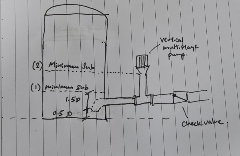
WhatsApp_Image_2022-02-25_at_10.17.19_lp5uzo.jpg


Thank you!

Nick
 
Replies continue below

Recommended for you

NPSHA is always calculated using absolute terms. It also must be given in terms of head of the liquid being pumped. The orientation of the nozzle doesn't effect the NPSHa of the pump except for the slight change in headloss of the elbow. Elbows that are downturned are used to allow the tank to be drained.

The pump manufacturer should be able to provide the NPSHr for the pump. Use the control system to ensure that the tank level doesn't go below that tank level.

If point #2 is the level that represents the NPSHr, then the water level should be keep above that level to avoid pump cavitation, not air locking.

Sometimes a vortex may occur on the intake and tank level should be kept above that point.

 
We need details of the pump. As drawn it doesn't look like a vertical multi stage pump.

It may be needed for static conditions but when operating you should be able to go down to min level.

Remember - More details = better answers
Also: If you get a response it's polite to respond to it.
 
Thanks for the quick response!

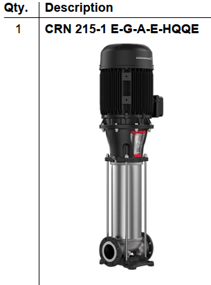
Apologize for my poor drawing, this is a Grundfos CRN Pump, hopefully this image would be useful.
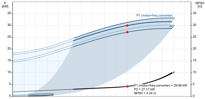
for NPSHr, it is about 4.24m, i believe it should not be a problem.

I am worried on the operating condition to stop the pump at minimum level.
Feed coming into this tank is inconsistent(depends on production) and therefore these pumps will be starting/stopping based on level.
And for this case i would like to stop the pumps when the level reaches (1) which is the most minimum level as per submergence calculations. instead of (2).


Capture_bqnqiq.png


Capture2_f8dwle.png
 
Put the check valve between the tank and the pump, this will allow the lower tank level you want while keeping the pump
full.

Not sure why NPSH has come into the discussion - where is no problem with the setup.

It is a capital mistake to theorise before one has data. Insensibly one begins to twist facts to suit theories, instead of theories to suit facts. (Sherlock Holmes - A Scandal in Bohemia.)
 
That's certainly one way to do it or can you lower the pump?

Remember - More details = better answers
Also: If you get a response it's polite to respond to it.
 
The CRN pump body have a vent hole that you can open and "prime" the pump with. As long as that vent stays shut and you don't drop the fluid level low enough to allow air into the suction of the pump the pump's case won't drain with the check valve in place. The pump needs to be fully vented of air and should be checked after a low level restart to make sure you didn't lose prime, but you'll only air lock the pump if you lose fluid and replace it with air.
 
Is there some reason why there cannot be an isolation valve between the pump and tank ?

IMHO, this type of pump is a particularly BAD CHOICE when paired with a plastic tank. Is this a "repurposed" pump that you already have ?

If this is a new installation, why not buy a more conventional horizontal axis pump ?

Grundfos CRN multi-stage pumps have a very marginal base mounting and are prone to vibration as the pump gets older and worn ... The pump is basically an "out of control" cantilever ..... This will spell disaster for the FRP plastic tank nozzle.

How are you going to anchor this old used pump ? .... is the baseplate cracked or broken ? .... Send pictures

Additionally, you are confused and should not be talking about "total submergence" and "minimum submergence" ..... it is not appropriate for this type of pump. An evaluation of NPSH IS APPROPRISATE .... Do not confuse submergence with NPSH !!!

MJCronin
Sr. Process Engineer
 
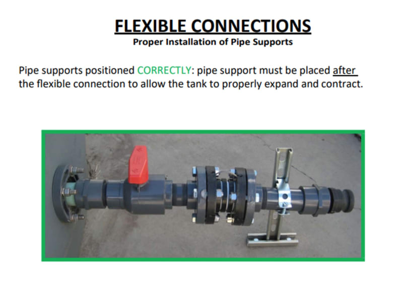
Agree with MJCronin's comments. It is good engineering practice to orient piping to allow plastic tanks to expand and contract.

Pict_neiv9g.jpg
 
Thank you all for the Valuable feedbacks!
I could spell out all the details here but i was only curious on the main question.

Yes the pumps is designed with manual isolation valves, drain valves for maintenance, pressure gauges at the discharge etc. The pumps also do come with expansion bellows on both suction and discharge to avoid all these issues with vibration. Basically it is a setup that a normal pump would have. I only drew out the check valve is it might be the main factor to discuss here.
Also, Why a horizontal is not chosen? Simply space cannot allow or else i would have chosen horizontal.

I am still talking about centrifugal pumps minimum submergence. Nothing on the NPSH of this setup.

It is true that minimum submergence is more of a common term used when selecting vertical pumps mounted on the top of the tanks/submersible pumps etc, It is not really a common term when we discuss on centrifugal pumps. However, in good practice, we still want to look into minimum submergence is due to things such as avoiding vortex creation on the "suction nozzle" to prevent air entrainment. Finding the best operating levels of the pumps.

Thanks again all for the inputs.

I have verified with the vendor also that the best option is to put a check valve between the suction and the pump as what Artisi has suggested(basically like a foot valve).


Status
Not open for further replies.

Part and Inventory Search

Sponsor