Continue to Site

Eng-Tips is the largest engineering community on the Internet

Intelligent Work Forums for Engineering Professionals

  • Congratulations KootK on being selected by the Eng-Tips community for having the most helpful posts in the forums last week. Way to Go!

Vertical Crack in A-Frame Cabin Roof Beam 3

Status
Not open for further replies.

SarBear

Structural
Mar 14, 2022
38
Hi everyone,

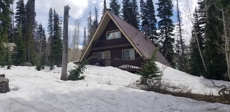
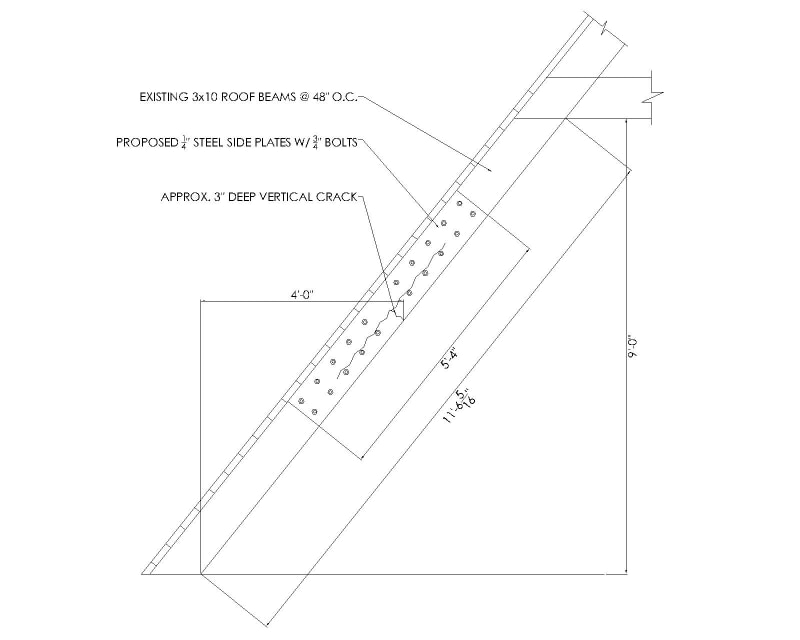
I'd like to get some input on this project I am working on. The client owns an A-frame cabin that was built in the 1960s in an extremely high snow load area (around 250 psf ground snow load). The A-frame is constructed with 3x10 beams spaced at 48" o.c. with 2x6 T&G running perpendicular to the beams. This last winter the client noticed that one of the beams had an approximately 3" deep vertical crack. As the snow melted away he noticed that the crack closed. Where the crack ends there is also a horizontal crack along the length of the beam that is around 40" long. The owner is asking us to provide a repair for the beam that doesn't involve replacing it altogether. I have attached a picture of the beam in question along with a proposed repair that I am working on. It is a work in progress, but my idea is to provide a 1/4" steel plate on each side of the beam and bolt through.

Before I get too deep into this I wanted to see what your opinions would be about recommending this fix to the owner. I haven't nailed down how long the plate would be and how many bolts I'd recommend, but do you think this general idea would be a good repair for the beam? Outside of this I can't think of any other reasonable fix for the beam. I appreciate any feedback you have. Thanks!
20230711_155554_haezig.jpg

Cabin_purlin_g8oprd.jpg
 
Replies continue below

Recommended for you

One concern to evaluate is having bolts on both sides of the rafter's neutral axis. Just because it could overly restrain the rafter's natural tendency to shrink and swell and promote additional cracking. Cabins tend to breathe a lot in terms of temperature and humidity, so it's something to consider.

You might look at a steel strap on the tension face of the rafter, with long timber screws that embed some distance beyond the longitudinal crack. The timber screws would be oriented perpendicular to the roof plane.
 
I would extend the steel plates to the floor and overlapping the second floor joints.

As alternate, can you sister another 3x10 beam the full length of the cracked beam? (up to the peak if no second floor in the area)

Are both the vertical and horizonal cracks thru the entire 3" thickness?
 
Another alternate along lines suggested by bone206, add a C-channel to the tension face with long timber screws.
 
I feel that the exercise of detailing a fix for this ought to be set aside until we've figured out a plausible cause for the cracking in the first place.

Was there an especially severe snowfall in the area last winter? Would something unusual have happend to alter the temperature or humidity within the cabin last year?

This is a structure with a 60yr+ history of successful performance after all. Something must have changed unless load duration finally caught up with it.

Does the vertical crack really extend across the entire width of the rafter? If so, that is difficult to see in the photo.

How do calculated flexural tension stresses compare to estimated allowable flexural tension stresses?

One interpretation of this is that it is a flexural tension crack that got disturbed by existing checking before it made its way across the entire cross section. However, if this is a flexural tension crack, it's the cleanest, straightest, least catastrophic flexural tension crack that I've ever seen in a wood member.

Another interpretation is that it started as a flexural tension crack at a knot or some other discontinuity but arrested itself near the neutral axis. The crack then became a tension side "notch" effectively which produced the horizontal cracking. Once again, however, the crack pattern seems cleaner than I would normally expect.

Either of these mechanisms would have me bypassing the damage with sistered members etc rather than attempting local reinforcement. Were I to reinforce locally, I'd probably be thinking adhesives and weird screws from Europe.

That roof is gloriously steep. I would have expected pretty great snow shedding. Are any photos of the snow buildup available?
 
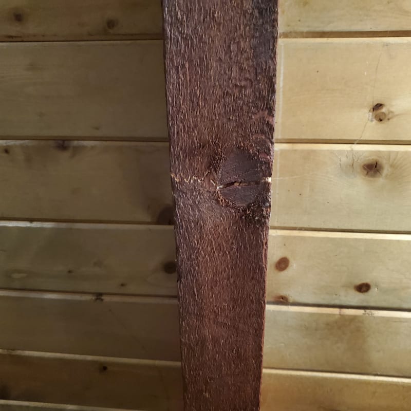
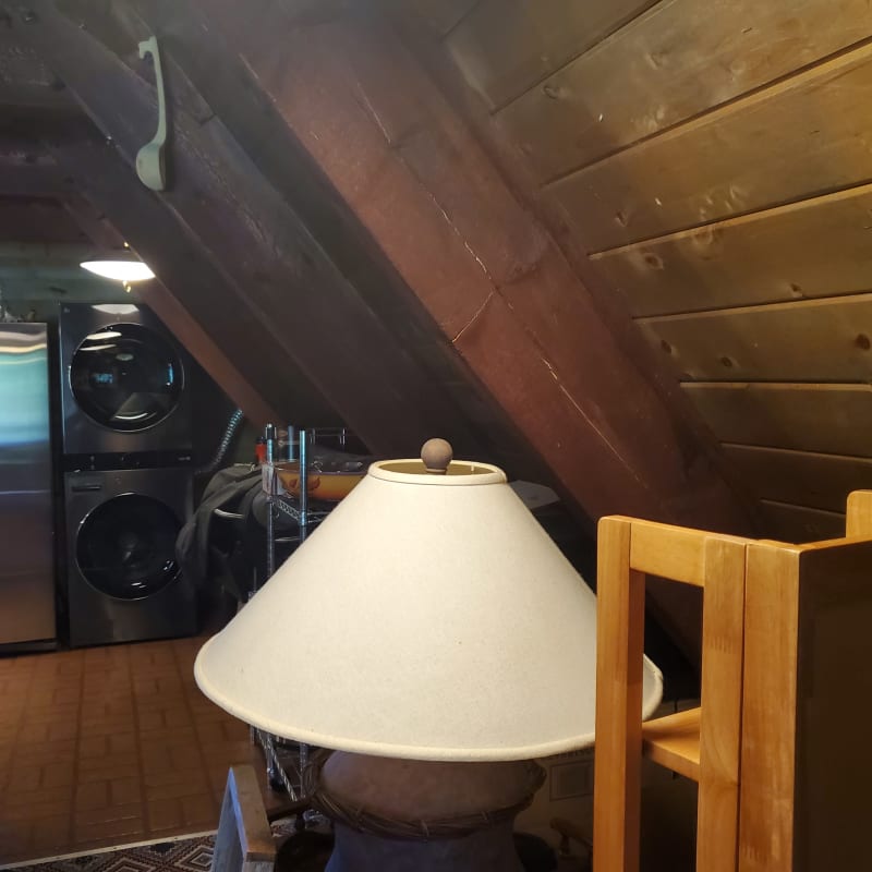
Here are some additional pictures to hopefully answer some of the questions that have been raised. The crack does go through the full 3" thickness and you can see a knot in the bottom of the joist. The area received the most snow it has seen in any winter since 1983 so I think it definitely was caused by the snow buildup. Over 900" of snow for the winter. Unfortunately I don't have a picture of the full snow buildup, but according to the owner the snow was piled up against the side of the roof more than halfway up the full height of the roof. Another part of the project I am working on is a new deck as you can see that a portion of the deck collapsed during the winter.

20230606_142109_xn3tzq.jpg
20230711_155547_wsa9n4.jpg
 
The crack started as a tensile failure around the knot in the wood, that turned into a shear crack through the center of the beam. The splice plate is needed over the knot. Lag bolts will hold the splice plate and close the shear crack. Injecting a two part epoxy into the crack would also be a good idea. Injecting cracks properly is not that difficult but it is more complicated that it may first appear. A little bit of vacuum and some plastic film and sealant can make the procedure quite robust and neat. The lag bolts should be installed starting at one end of the splice plate, moving toward the knot in the center, then start again at the other end. this should help to close the cracks.
 
If you've got a knot like that in the middle of the member at the extreme tension face, I'd wager that you're dealing with ungraded / poorly graded timber. The flexural capacity of such a member can be both very low and wildly unpredictable. You'll want to factor that into your expectations for future member performance if you go with a localized repair. That, or you effectively "grade" the member yourself.
 
Just to clarify, when I said steel strap I really meant a strap fabricated from plate stock. Not like a Simpson type strap.

Put a bunch of big ASSY screws into it and see what kind of capacity that gives you. You could even get them with countersunk heads and make it look nice. The nice thing about those long screws is that they can act as shear reinforcement across the existing longitudinal crack, while also taking the bending shear flow into the strap.
 
I think bones's approach would be what I would do.
 
If a 3x10 was adequate to begin with, then a high grade 2x10 (or two) sistered to both sides would surely be the lowest cost solution if the aesthetics of that would be palatable to the owner.
 
While the beam did fracture at the knot it also managed to withstand the load with some additional deflection. There should be some manner to splice in another wood piece to bridge that gap other than with steel strapping or bolts.

For example - if one were to create an X cut down to the split and epoxy in replacement wood of the same species - one piece from each side in what would basically be a shallow V then the scarf joints would be adequate to take the load. Find a finish carpenter to do the work so the glue line is well made and then plane it flush on each side.

In aircraft they are about 10:1 so each 1.5 inch deep scarf will need to run only 15 inches each way; overall a 30 inch long repair. In aircraft they usually bond another layer to prevent the ends from peeling due to bending across the scarf but that seems unlkely to be a problem here. One could leave the scarf end above the existing beam and chamfer it to provide more than a feathered edge at the end.

This would also allow cleaning up the split where the scarf goes for a better bond with the scarf piece and make for a shorter path to insert epoxy into the remaining crack
 
3DDave,

This is a cabin in the mountains, not an airplane, or a piano.
 
It's wood. Not marring it with a metal plate destined to damage people or furniture would be a benefit.
 
May e worth considering the possibility that this crack isn’t tension, but compression failure.
Before modern grading, lumber was visually graded and not mechanically stressed, so brashness from felling the tree could get passed over, resulting in failures like this later down the road.
 
I second KootK's suggestion. The wood reinforcement will swell/shrink with the existing rafter.
 
Thank you all for your suggestions. I think I will propose bones's solution with a beefy strap/plate on the bottom and also Kootk's suggestion of some sistered members to the owner and see what route he wants to go.
 
Status
Not open for further replies.

Part and Inventory Search

Sponsor