Continue to Site

Eng-Tips is the largest engineering community on the Internet

Intelligent Work Forums for Engineering Professionals

  • Congratulations MintJulep on being selected by the Eng-Tips community for having the most helpful posts in the forums last week. Way to Go!

Vertical Offset in Diaphragm Chord 1

Status
Not open for further replies.

StrEng007

Structural
Aug 22, 2014
515
I've reviewed the text from "The Analysis of Irregular Shaped Structures" and it briefly talks about vertical offsets in building chords. However, there isn't much discussion on how to design or detail this condition for different scenarios.

In the image below, I have a rectangular shaped building. The following is assumed for the point of this discussion:
[ul]
[li]Diaphragm is flexible.[/li]
[li]Diaphragm shear is transferred directly to the top of the perimeter tie-beam.[/li]
[li]Lateral load in each north/south & west/east direction is the same unit value at 400 PLF.[/li]
[li]There is a 3ft vertical offset at the tie-beam, along line B, from the center of the building due east. No other vertical offsets occur.[/li]
[li]Plane of the roof diaphragm is the same at all locations (ignore slope requirements) of the building via varying truss heel heights. There exists proper detailing to transfer all loads to top of tie-beam as previously mentioned.[/li]
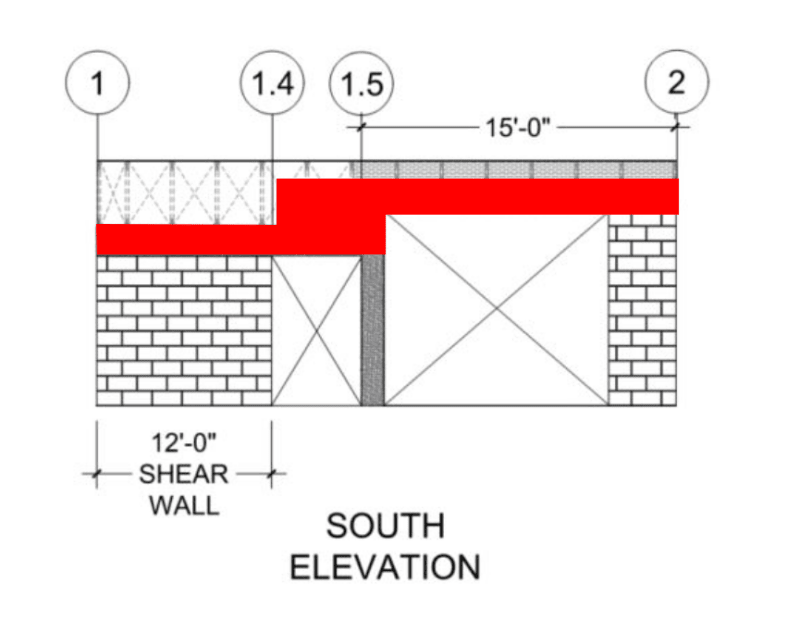
[li]South elevation has (2) openings separated by a CIP concrete column. Left side has a shear wall. The only lateral force resisting components along line B are the shear wall and tie-beam system.[/li]
[li]All other exterior lines have adequate shear walls.[/li]
[/ul]
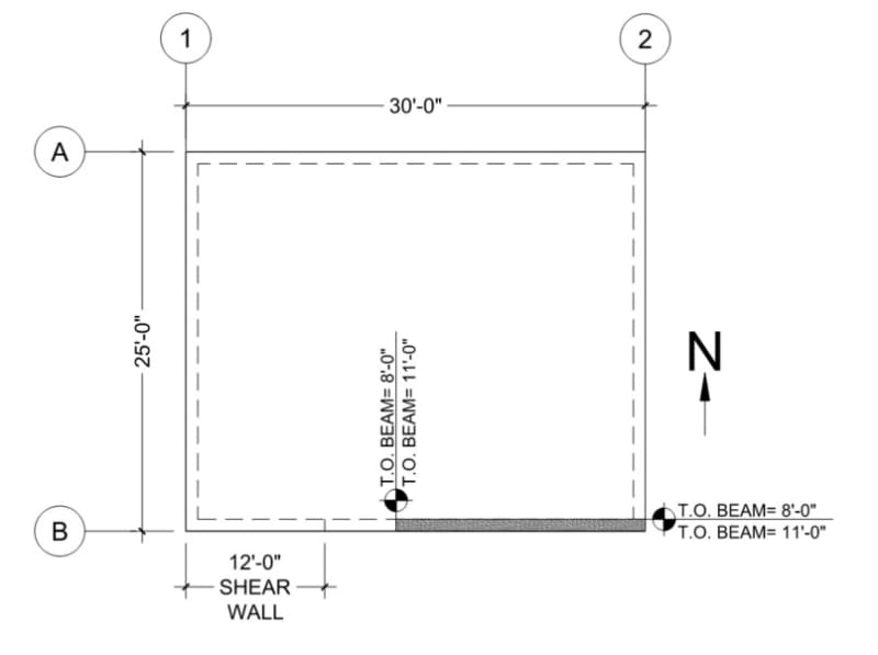
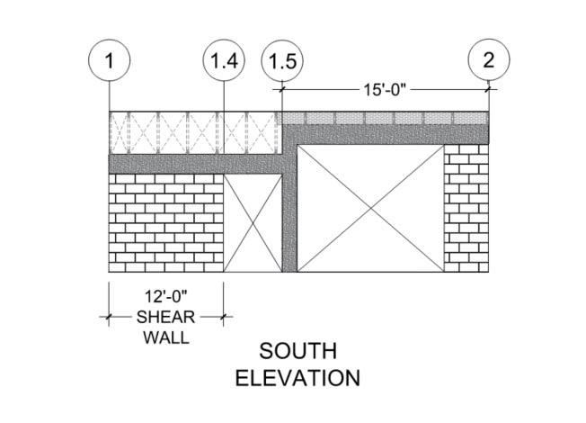
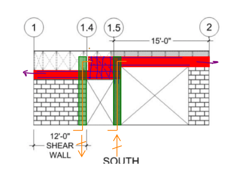
Image1_sbskcq.jpg

Image2_iyrdkh.jpg


Question #1:
For transverse wind (north/south) the maximum chord force in lines A and B is:
400lb/ft x (30ft)²/ (8 x 25ft) = 1,800 lb

How is this chord force transferred across the vertical step in the tie-beam?

Question #2:
For longitudinal wind due east, the tie-beam is acting as a drag that is pulling away from the shear wall.

Diaphragm shear at line B = 400lb/ft x (25ft /2) = 5,000 lb

Shear in wall directly from the diaphragm = 2,000 lb
Drag force at 1.4 is 3,000 lb tension (due east)
(This sums to the total lateral force of 5,000 lb)

Drag force in tie-beam at 1.5 is approximately 2,500 lb tension (due east)

Similar to Question #1, how is the drag load continuous at the step in the tie-beam?
 
Replies continue below

Recommended for you

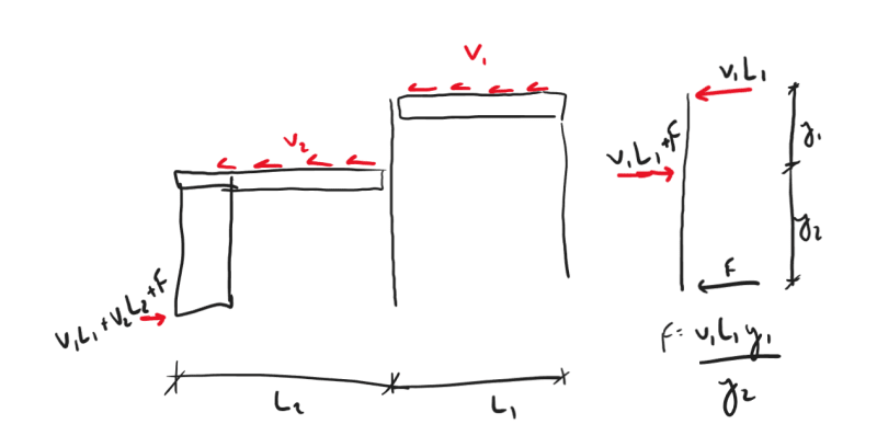
You have a beam column at the step. Attach your chord elements to the beam column with straps and through direction bearing for tension and compression loads, respectively. Draw a FBD of the beam column and you can design the beam column easily enough.
 
Agreed with Pham I've had to do this quite alot especially on custom homes. You want to limit lateral deflection of the beam-column because it will contribute to diaphragm deflection and its not a simple task to try to determine by how much. I suppose you could add a fixed number to the chord term of the deflection equation.

Another thought would be to try to make the chord occur at the top of the joists so that it can be continuous. Strap over blocking.

The beam column would also be part of the drag load path, its not ideal but what ya gonna do. You 2500 # isn't huge though strap over blocking could easily handle this.
 
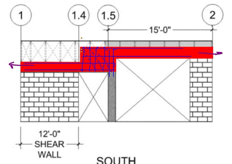
I too agree with phamENG in principle. For a high seismic situation, promoting a shear failure across a column is kind of sketchy though. Were I in a situation where I was not comfortable with that, I'd probably push for a solution like that shown below. It echoes how stepped masonry bond beams work as chords and collectors.

C01_wlgrjz.png
 
I knew I could grab the attention of you three with a good question setup and some sketches. Thank you.

phamENG said:
Attach your chord elements to the beam column with straps and through direction bearing for tension and compression loads
Good suggestion. Original intent was to have this beam-column perform for gravity and as a wind column for out-of-plane wind loads.
For this scenario, whether question #1 or #2 (especially question#2), is there any other theory than to require moment fixity at the base of this beam-column? I was trying to stay away from that. That's analogous to a very short shear wall without any aspect ratio, and thus becomes just a cantilever column? So then I'd be back to comparing the relative stiffness of the shear wall vs that of the beam-column (modulus of shear and all that good stuff)?

driftLimiter said:
Another thought would be to try to make the chord occur at the top of the joists so that it can be continuous. Strap over blocking.
Blocking over the top of the truss heel or inline with the top chord (top of truss = top of blocking)? I see this as fixing the chord issue but not the collector issue.

KootK said:
stepped masonry bond beams work as chords and collectors
Good suggestion. I'll typically step a CMU bond beam over one course at a time. Say a 10ft run of T.O. 16" bond beam at +10'-0" will step down to T.O. bond beam at 9'-4" and I require that overlapping length a minimum 16". Similar with foundations, I'll step T.O. footing at 2'-0" maximum intervals over a 4ft length (combination of industry standard where I am and what I'm comfortable with). With your suggestion, stepping at 3'-0", do you have a special reinforcing pattern in mind?
 
No need to fix the base. The reaction at the base should be just be shear to balance the moment from the offset chords unless you want it to be a shear wall.

Something kinda like this:
Screenshot_2023-08-07_110056_sljjta.png
 
StrEng007 said:
With your suggestion, stepping at 3'-0", do you have a special reinforcing pattern in mind?

Nothing too exotic. It's basically just a version of an offset lap splice. When I can get away with it, I see that as being one of the benefits of intelligent proportioning: it often obviates the need for fancy rebar detailing. Here, "fancy" probably just means some dense column ties between / through the tie beams. And some attention to overstrength and capacity design principles if it's a high seismic thing.

c01_dubygw.png
 
phamENG said:
Something kinda like this:
I understand the right hand side of your FBD. However, it feels to me like the overall approach is doing something strange to the unit shear in the collector. I'm trying to simplify this model by calculating it using a quasi method of sections, where the beam-column is a brace point. Bear with me as I try to explain my approach (I need a sounding board).

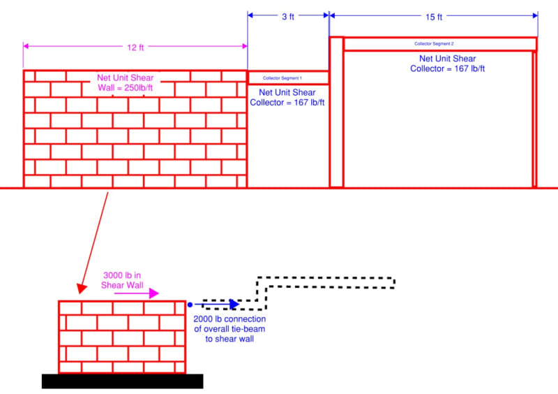
In the image below, I'm representing the overall lateral line comprised of a shear wall and a collector (that jogs). I've shown the net unit shear in the shear wall and the collector. Below that is an idealized model of the shear wall, which shows the overall 5K lateral load being resolved down to the foundation.
Image3_xoetlt.jpg


Applying your approach for the intermediate collector force at the beam-column, I get the same magnitude of force that you did.
Image4_elfbyb.jpg


Now this is what throws me off. Using the same reactions and doing a logic check on the 3ft section of collector, I don't get a value that matches my original assumption for the net unit shear in the collector.
This throws me for a loop against any problems I've read where calculating unit shears is either a function of a collector/drag or a shear wall (never an intermediate beam-column).

Image5_pvwzcd.jpg


I realize this: (3437.50 lb - 2000 lb - 937.50lb) / 3ft = 166.67 lb/ft

However, this would beam that I have two different unit shears in the collector and a different connection load from Collector Segment 1 to the shear wall. I'm just not too familiar with this approach. I hope I summarized where I am coming from.
 
I think your math is a little off at the "connection of overall tie beam". 167plf(3ft+15ft)=167*18=3006lbs, not 2000lbs. So....(3437.5-3000)/3=145plf. That's closer. BUT...your 3000lb tie force presupposes that the ONLY loads in the collector are from directly applied diaphragm shear. The offset makes that incorrect. You need an additional axial load in that 3' piece to make the couple that counters the moment induced by the offset collector.

So rather than assuming a tie force, you should apply all the loads and work back to it. I'm guessing you'll come up with 3,937.5lbs for your tie force.

 
phamENG,
Yeah you're right. In my OP I had 2,000lb in the wall and 3,000lb connection force (which is correct). Somehow, I flipped the two values when putting together that sketch, then (enthusiastically) ran with it.

So to clarify, diaphragm shear connection remains as 166.7lb/ft along the collector. It's just the collector to shear wall connection that needs the additional force. Thank you for illustrating this. It's interesting... I haven't really seen this described in our texts before.

What would your approach be for the chord force at the beam column? It has each and opposite forces, which varying heights. This is independent of the shear wall, so how would that balance?
 
For clarity the shear wall force (2,000 lb) and collector force (3,000 lb) were flipped to match the correct loading in the OP.

Based on our discussion, a revised overall model is calculated below. Note the base shear in the shear wall is 5,937.50 lb but the overall sum of base shears for the entire model (two foundation segments) maintains the overall 5,000lb from the OP.

Image6_fhvu5y.jpg


The model makes sense and I can see where all the loads go. What is interesting to me is how this model shows the additional tension at the connection of Point 1.4 (due to the offset of the tie-beam), but it does not alter the collector net unit shear from 1.4 to 1.5. I keep wanting to associate this load as being dragged through the collector and thus I'm anticipating a higher diaphragm connection than 166.7 lb/ft along this 3 ft segment.
 
StrEng007 said:
I keep wanting to associate this load as being dragged through the collector and thus I'm anticipating a higher diaphragm connection than 166.7 lb/ft along this 3 ft segment.

I suppose that's fair - in most cases, these are handled very simply. Base shear of shear wall = applied wind loads, done. So our brains tend to default to that. But there are these cases where the arrangement increases the forces in the lateral force resisting system. You just have to keep in mind that the collector load is being applied by the diaphragm (which is being loaded from the out of plane walls) and the 'additional force' is coming from a reaction at the beam column. So the collector force is a Uniform Distributed Axial Load, while the additional load is a Point Axial Load.
 
ooh, what about using the jambs to resolve the OTM on the dragstrut over the door?

1_u46fmj.png
 
Boiler06 said:
ooh, what about using the jambs to resolve the OTM on the dragstrut over the door?

Oh yeah... mechanically glorious!
 
Boiler06 said:
jambs to resolve the OTM
I already had to stare at this "additional collector load from moment induced drag" long enough... last thing I want to do is start looking at a moment frame stuck to the end of a shear wall.

My actual building can handle these loads with ease. It's the theory I'm after...
 
StrEng007 said:
... last thing I want to do is start looking at a moment frame stuck to the end of a shear wall.

It's not a moment frame. It's a highly rational way to resolve the moment that the vertical offset in the collectors would induce in my proposed "super blob". Right column would be in compression and the left in tension based on Boiler's sketch. And shown in Boiler's sketch.
 
But isn't 1.4 going to be the chord of the shear wall segment that is in compression?
 
StrEng007 said:
But isn't 1.4 going to be the chord of the shear wall segment that is in compression?

Yeah that sounds about right.

7v9nca_bjnkxh.jpg
 
Status
Not open for further replies.

Part and Inventory Search

Sponsor