Eng-Tips is the largest engineering community on the Internet

Intelligent Work Forums for Engineering Professionals

Very Strange Occurrence with Roll Pin 3

Status
Not open for further replies.

Jason3w

Mechanical
Sep 26, 2016
3
0
0
AU
Hi all.
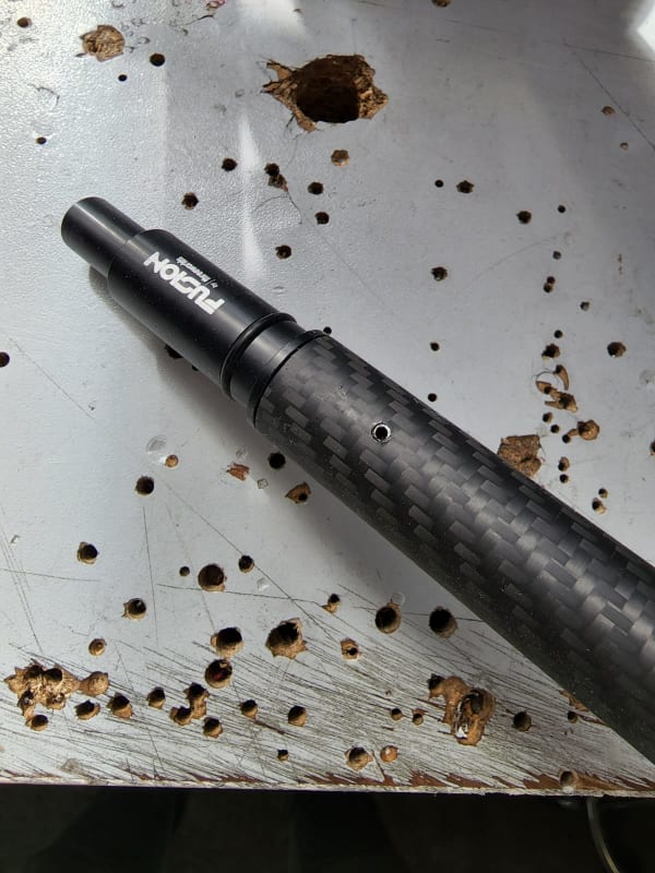
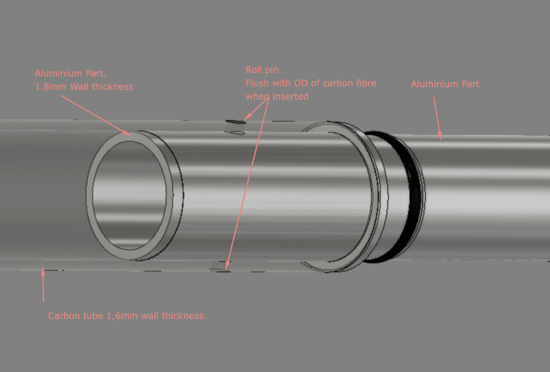
We currently use a 3mm roll pin to secure an aluminium component inside a carbon fibre tube.
We drill a 3mm hole through the two parts and use a hammer with a decent force to insert the roll pin.
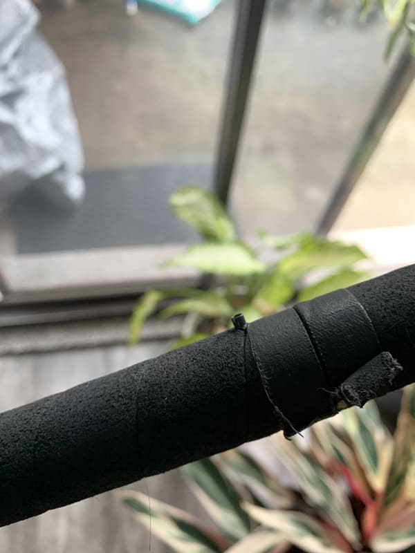
We have reports from customers of the roll pins working their way out of the two parts somehow.
The final product is a 1.5mt pole that is spinning when used and forces are applied to the centre of the pole with weights on the ends.
This is entirely baffling which is why I am here to see if anyone could explain why/how this could happen.
The two parts have very tight tolerance and we also use Araldite 2015 to glue in place prior to pinning.

Any ideas how this happens?
Images attached.
Thanks!

Pin worked out on parts and through the EPDM grip.
pin_ik3eit.jpg


pinissues_qblkpy.png
 
Replies continue below

Recommended for you

Roll pins are typically tapered on the ends so they can be installed, so I expect it's just using one end as a wedge and as soon as it starts in one direction it keeps going. In addition, being roll pins, they can be compressed by the applied load and it seems like this application is to just keep working it back and forth. As it compresses it isn't completely round and leaves a tiny gap that allows a tiny movement. If there's the slightest lack of perfection in the contact that will bias the movement.

I had the experience of something similar - a 6 inch diameter X 12 inch long press-fit bushing that was rotating in the part it was pressed into. Under the applied load the pre-load was exceeded leaving a very small gap on one side and allowing it to rotate much like a harmonic drive gear would. I think that was 0.010 - 0.015 press fit.

I've seen spring-steel /spring band/ hose spring band clamps that might help. Cut off the ears and it's a low-profile retainer that, slid over the roll pin, will stop the roll pin from starting its migration. Alternatively, try a more precise hole making operation and use a solid pin? Not sure. Without a stop against a degree of freedom in an oscillating device it's hard to control movement. See (no affiliation and not a recommendation - for picture purposes only.)
 
Hi Dave.
Thanks for the response.
You are correct, the roll pin does have a tiny taper on the end, though both ends of the parts are open and the bevelled edge wouldn't be in contact with the parts at all.
The use case has a very low RPM and is operated by hand.
You can see it in use here.
The suggestion of using a solid pin is an interesting one. Our other issue is that it is extremely hard to test for as this happens rarely out in the field and must require a lot of movement to occur.
So we could change pins only to find out in a few months that it's worse. Hmmm...

This image shows the actual part with pin inserted.
WhatsApp_Image_2022-07-25_at_2.39.35_PM_ophshk.jpg


The roll pin is like this. Tiny bevel on one end only for ours.
[URL unfurl="true"]https://res.cloudinary.com/engineering-com/image/upload/v1658724070/tips/F0374020-01_umwyvq.webp[/url]
 
Are you drilling with a 1.5mm drill bit?
If so then your holes are likely oversized.
Take a batch of drill bits and measure each one (to 0.01mm or better).
Sort them by size and then drill some test holes.
I think that you will find that many of the holes from larger bits are noticeably over 1.50mm.

= = = = = = = = = = = = = = = = = = = =
P.E. Metallurgy, consulting work welcomed
 
Do you do QA on the orientation of the pin?

I.e. if the open part of the pin is in line with the axis of the rod then its more likely to get squeezed due to torsion between the two poles, but make the open part 90 degrees different and it would need axial movement to squash the pin.

Maybe need more pins? or just fill the pin with glue or a more solid pin inside the split pin as well as the pin itself.

But that thing looks like it has all manner of forces when in use so not easy to figure out which is the worst - axial force or torsion.

Remember - More details = better answers
Also: If you get a response it's polite to respond to it.
 
You could use a rivet and swage the end, unless you can't protrude beyond the OD of the CF tube.

If you're sticking with a split roll pin I'd suggest a bit better installation method. A press would likely avoid the damage seen in the photo, as would using a 3-punch installation sequence; roll pin holder punch, flat brass punch, roll pin set punch.

These pins are one time use as well. They'll have a higher tendency to walk out if they've been driven out and reinserted.
 
Maybe if I use a more technical term like acrylic adhesive it will gain more traction than "glue". The geometry is perfect for an adhesive connection.
 
Because of the thin wall. No solution is easy. Roll pins from experience once damaged will fall out. Or work their way out. Thus are a pita.a solid pin in my opinion is better but not the solution.
I seen rivet used in application like this when it is possible. Next best it extra strong adhesive.
 
I have used those pins in hinges on products sold in the millions. Unless we flare the ends they will work their way out. 0.0001" of movement times 1,000 cycles is 0.1 inches.

I agree with the suggestion of eliminating the pins and gluing it together. There are aerospace applications with CF bonded to AL that had better fatigue life without the rivets.
 
We drill a 3mm hole through the two parts and use a hammer with a decent force to insert the roll pin.

If your only machine op is the drill then you’ll end up with bores varying significantly in both size and roundness. Quite often 2-flute drills make 3-lobed bores, which won’t give much friction against a round roll pin so they’re going to walk out. Standard practice for roll pins is to ream to final size bc of it. With concentric bores like shown, the outers should be clearance bores so the inners can retain the pin regardless of relative motion between parts.
 
Thanks, everyone for these very insightful and useful nuggets of wisdom.
What a great community and a wealth of knowledge!
We will take a number of these tips and adjust our production accordingly.
Much appreciated!!
 
Let us know what you decide to do and send a picture.... That's the payback we like people to do. Many don't.

Remember - More details = better answers
Also: If you get a response it's polite to respond to it.
 
Status
Not open for further replies.
Back
Top