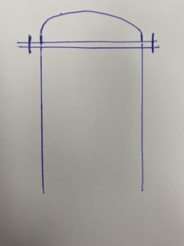
I've got a ASME Div 1 pressure vessel that needs to be designed for relatively low pressures (+10 psig to -2 psig, @ 275 deg. F) and I have a question about a flange that separates the cylinder from the F&D Head. The image below shows the location, so they would be able to pull the whole top of the vessel off from the cylinder.
It's my understanding that I've got two choices for this flange, Appendix 2 or Appendix Y.
For Appendix 2, I need to apply 2-14 Rigidity calcs per the latest code requirements, and I get a flange thickness of over an inch to satisfy the rigidity at gasket seating calculations.
For Appendix Y, I can't show the vessel as being rated for any amount of external pressure per ASME Interpretation VIII-1-95-16 and Y-1(b). So, I can't have any type of vacuum rating on this vessel if I were to use this type of flange. It does allow for a thinner flange to meet the external pressure requirement since the calculation requirements are different.
My issue is that they want a thinner flange than what I calculate with Appendix 2, but I don't see how I can provide a vessel rated for vacuum pressure any other way.
Any thoughts or comments would be greatly appreciated. For now, I have told them they need to use the Appendix 2 flange with the calculated thickness.

