Eng-Tips is the largest engineering community on the Internet

Intelligent Work Forums for Engineering Professionals

VFD blow up 8

Status
Not open for further replies.

james64

Electrical
Oct 16, 2012
46
0
0
CA
Hi all,

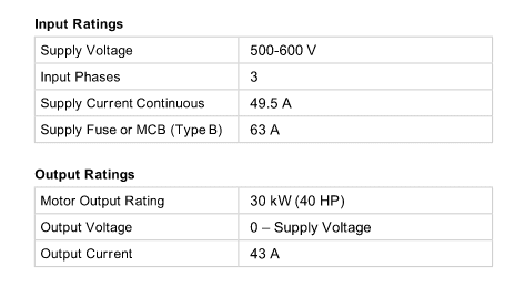
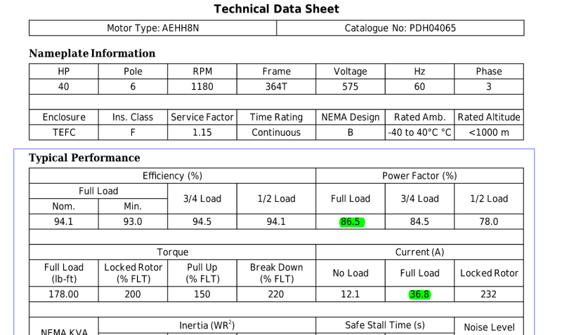
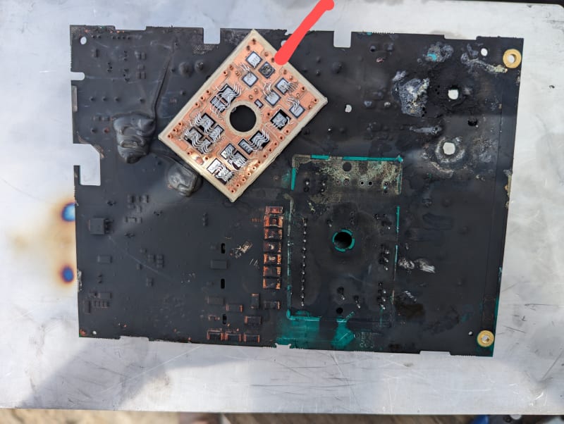
I am experiencing a problem with a VFD that seems to be getting damaged when the motor starts. The overcurrent protection of the VFD is set to around 70A, while the motor has a full load current of approximately 80A, 600V, 3-phase at FLA. I am wondering whether the issue may be caused by an inrush current or other reason.
 
Replies continue below

Recommended for you

You have 100% control over inrush current with a VFD. Your failure is occuring for other reasons.

What do you mean by damaged?

How many times has damage occurred?
 
First start? You're on the left hand side of the bathtub curve. I would suspect a defect in the drive. Have you reached out to the manufacturer about warranty? Their response might help identify the root cause. In my case it was replaced no questions asked which indicates that they have experienced many commissioning failures.
 
How is the VFD set up to start?
Ramp rate?

What is the load doing at the start?
Do you have data on current vs time?

How old is it?
What did the vendor say?

Remember - More details = better answers
Also: If you get a response it's polite to respond to it.
 
Thank TugboatEng and LittleInch,

TugboatEng,

I will contact the vendor.

LittleInch,

Wil more investigation about that. See below for your concerns.

How is the VFD set up to start? => Can you please elaborate on this question?
Ramp rate? => VFD units are factory set with acceleration and deceleration ramp rates set to 30 seconds.

What is the load doing at the start? => 40HP, Exhaust fan
Do you have data on current vs time? => Will ask the vendor to provide it

How old is it? => A few months old
What did the vendor say? => Waiting for vendor's response.

 
600V rated VFDs are a tricky thing. The transistors for them represent less than 10% of the test acceptance rate of the production lines. That means when testing the transistors to fill an order for 100 units tested for use at 600V, 900 will have failed and must be scrapped, making the 600V tested transistors very expensive. Some “bargain” drive manufacturers chose instead to use transistors that passed at 480V, which are less expensive, and take their own chances (with their customers) on the survival rate in the field. You may be suffering from this decision making process.


" We are all here on earth to help others; what on earth the others are here for I don't know." -- W. H. Auden
 
Thank jraef for your comment.

You mentioned that only a 10% success rate can be guaranteed for 600V, which indicates a high potential failure rate for the drive side.
 
If you are trying to start a motor that is already turning (flying start), then you need to set the drive up to accommodate that. Otherwise you will see very large currents as the drive tries to start the motor thinking it is stationary.

Brad Waybright

The more you know, the more you know you don't know.
 
The motor is sized at about 80 kW for a 30kW load?

And why set the overcurrent at 70A for an 80A FLC motor?


Remember - More details = better answers
Also: If you get a response it's polite to respond to it.
 
Thank thebard3 and LittleInch,

To thebard3,
I agree with your comment.

To LittleInch,

After reviewing the shop drawing, I noticed that the specification lists two full-load currents. Please refer to the attached file for clarification. I am a little confused about which one I should consider it.
VFD_specification_qbkded.png
Exhaust_Fan_iqzmek.png
 
43 Amps is the maximum VFD current.
The motor full load current is 36.8 Amps
40 HP, 575 Volts, 94% efficiency and 86.5% Power Factor correlates with 36.8 Amps Full Load Current.

--------------------
Ohm's law
Not just a good idea;
It's the LAW!
 
James,

I am astonished that you do not seem to know how to read a simple table.

The header row of the bigger number clearly says "Power factor (%)"

The lower one clearly says "Current (A)"

So there is only one FLA, not two.

You still haven't answered most of the questions asked. Like what exactly is the "damage"?

Also what is the load? Can you find the fan curve.

Remember - More details = better answers
Also: If you get a response it's polite to respond to it.
 
Thank Waross & LittleInch,

I spoke with the contractor, who informed me that the VFD had broken into pieces with a loud bang on the floor. He remembered that the fan operated correctly for a few months. He also mentioned that he does not have any information regarding your concern. I plan to visit the site next week to gather more information and site photos.

The load is the exhaust fan which was given clips earlier. I am not quite sure if the operation was done properly as per fan curve. Attached is the fan curve.
FAN_CURVE_yzzsic.png
 
A fan will put extended stress on any starting system to overcome inertia. I'm sure you have taken this into account. Lots of mention of the fan motor and the VSD but nothing about the cable between them and in particular the length of that cable. Have you got a choke involved?
 
Thank SilverfoxUK for your comment,

As far as I know, VSD is located near FAN and I will verify the distance of the cable. However, the fan has been operated on for a few months without a problem, this issue came out recently. I am skeptical that issues with the reason, harmonic, or fan insulation could be the cause of this problem.
 
"Broken into pieces with a loud bang" - What ???

Sounds like complete destruction and huge internal shorting, not "damage when starting".

And if it was working OK before then this is a simple failure of a unit which should be in its warranty period so sweep up the bits and return them to the vendor and demand another one or your money back...

Remember - More details = better answers
Also: If you get a response it's polite to respond to it.
 
Loud bangs and VFDs are never an application or programming issue. Never. This is either a component failure issue or an EXTREME voltage event. The only thing that can suffer a “Rapid Unplanned Disassembly Event” (RUDE) like that inside of a VFD are the capacitors. Capacitors can fail for a number of reasons, but rarely go RUDE unless it is something really big. I would be looking at the power quality at this site with an eye toward big events. If it has happened more than once, that’s even worse!

James64 said:
You mentioned that only a 10% success rate can be guaranteed for 600V, which indicates a high potential failure rate for the drive side.
No. The testing and failure rate takes place at the manufacturer of the transistors. The ones that get USED by (responsible) VFD manufacturers for 600V are already proven to be good. The issue I was raising is that there are some “less than responsible” VFD manufactures selling “600V” drives who choose to keep their costs down by using transistors that have only passed at 480V. They then take the financial risk of having to replace 600V drives that fail in the field under warranty (because they will generally fail fairly fast). The flaw with that philosophy is that even if the users get a replacement drive for free, they suffer down time losses and maintenance time to swap them out.

Another thing though, and please, I know it seems far fetched but I HAVE experienced this more than once and it does foment a RUDE event…. Did someone accidentally connect the line to the load terminals and vice versa?


" We are all here on earth to help others; what on earth the others are here for I don't know." -- W. H. Auden
 
I wouldn't say only the capacitors. I just had a VFD blow up starting with a diode failure that led to a sustained arc flash resulting in lots of catastrophic damage.

PXL_20230929_195133096_2_htrzvd.jpg
 
Status
Not open for further replies.
Back
Top