Eng-Tips is the largest engineering community on the Internet

Intelligent Work Forums for Engineering Professionals

VFD in a lathe application 5

Status
Not open for further replies.

itsmoked

Electrical
Feb 18, 2005
19,114
0
0
US
Hi, does anyone have the rundown on using a VFD'd motor in a lathe?

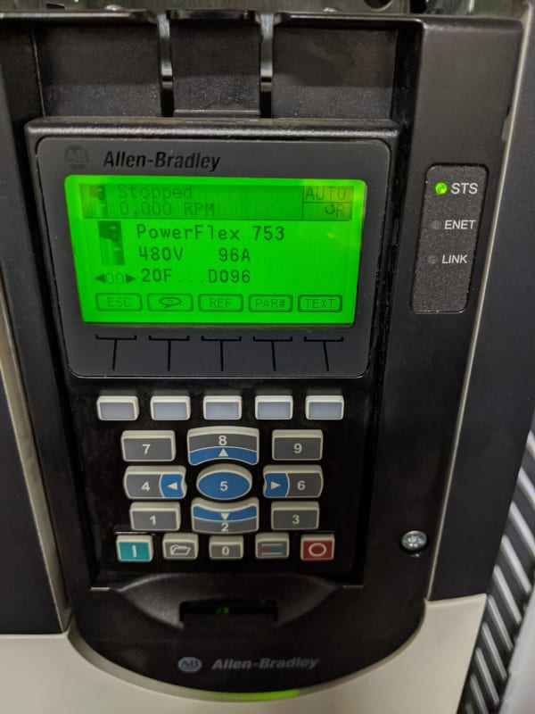
We've put a 5hp VFD specific motor into a Monach lathe. The original motor was a DC motor run by tubes! This was later swapped out for SCRs in a DC controller in the 80's. That's crapped-out just like the company that made it and as a last resort we put in this VFD induction motor that even came with an encoder.

I'm running it in sensorless Vector mode since we're not trying to do positioning or holding.
Tuned it successfully with nothing attached to it. Hooked it up to a gear box whose output belt drives the spindle.

The lather came with 1hp, 3hp, and 5hp options.

Everything operates fine except at lower speeds you can grab the spindle and stop it with your hand. While I don't expect massive low end torque that's seeming... under-the-bottom.

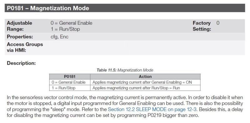
On a second note I see large currents being sent into the motor even if it's stopped. !4A FLA and I'll see maybe 10A, .8A, 4A on the phases when the motor is stopped. Is that the drive trying to keep the rotor somewhere known? Can that be avoided?

Keith Cress
kcress -
 
Replies continue below

Recommended for you

I don't understand what do you mean by "drive status should be "running" and not stopped"?

“Logic will get you from A to Z; imagination will get you everywhere.“
Albert Einstein
 
On the HMI for the drive, the ones I have seen usually have some sort of indicator of what the drive is doing. If the drive is controlling the motor it will say "running". If the drive is not controlling the motor it will say "stopped". Braking would mean the motor is under control of the drive and it will indicate running. Coast to stop means the drive is not controlling the motor and will indicate stopped.

This is an example from my phone.

IMG_20191227_141838_mqqmtb.jpg
 
I can't use coast-to-stop as this is a lathe and the users always want it to stop INSTANTLY even though that's idiotic and I have to ask them if they also want the work piece ejected into their faces and if they want to replace all the motion hardware every two years. That usually gets them to reduce their expectations out to something like 3 seconds... Coast would take 60 to 300 seconds.

I'm not using DC braking as there's a BIG braking resistor and this is an oversized drive so 3 seconds should work. DC braking dumps a ton of heat into the motor.

Keith Cress
kcress -
 
Itsmoked said:
I just wish the excitation would go away since one expects a lathe to spin freely when "STOPPED" and I'd like a stopped period to go towards cooling the motor where still cranking 10 amps thru it doesn't probably allow any net cooling.

Itsmoked said:
I can't use coast-to-stop as this is a lathe and the users always want it to stop INSTANTLY

Okay I misunderstood, I thought you wanted it to "spin freely"/coast. :)

You meant after it stopped you wanted it to be powerless?

“Logic will get you from A to Z; imagination will get you everywhere.“
Albert Einstein
 
I agree with Curt, this could be the magnetization current, also sometimes called "flux-up" current, meaning the drive pre-establishes the motor flux to reduce the time it takes for the torque to get to the shaft. It might be that your "Stop" signal is not set as a true Stop, as in it is a "Zero Speed" command, which is not the same in a VFD, especially one under any kind of vector control.

Looking at the manual, I'm wondering what you have P0229 set for, the "Stop Mode" selection. Do you have it set for "Ramp to Stop" by chance? If so, and you have the Decel Ramp TIME set out long, even if the LAOD causes the motor to come to a stop, the DRIVE will continue that decel ramp of the output for the full amount of Ramp time. Then if you have P0229 set for "Quick stop", it uses the setting of P0106 as the Decel ramp time, and the factory default is 5 seconds, but someone could have set that longer too. Also look at P0300, which is the DC Braking Time at Stop. With DC Injection Braking, DC current is sent into 2 poles of the output. If that is turned on, then look at the next couple of parameters, which are the frequency at which is begins to brake and the voltage of that DC injection. Any of those might be causing what you are experiencing.

D'oh! Didn't scroll down all the way before responding...
Never mind!


" We are all here on earth to help others; what on earth the others are here for I don't know." -- W. H. Auden
 
cfw500 programming manual 11.2 I/f MODE (SENSORLESS) said:
The minimum speed recommended for the operation of the Sensorless Vector Mode is 18 rpm for 60 Hz IV pole motors, and 15 rpm for 50 Hz IV pole motors. If P0182 ≤ 3 rpm the inverter will always operate in Sensorless Vector mode, i.e., the I/f function will be disabled.
If your users need torque at speeds slower than 18 r/m Vector with encoder will get you there, but at zero speed unless intentionally set to freewheel, the motor will lock in place with current proportional to the force the operator applies to rotate the spindle. At zero speed no torque voltage will be very low, and current will be close to magnetizing current. If you need freewheel, do that command after a short time delay.
I did exactly this in a hoisting application. IE motor to a stop with test torque applied, set the shoe brakes, then set drive to freewheel after time delay. and also the reverse.
But with a hoisting duty drive (now obsolete) so I am not going to suggest programming. Enough good hints above.[wink]
 
Status
Not open for further replies.
Back
Top