Eng-Tips is the largest engineering community on the Internet

Intelligent Work Forums for Engineering Professionals

VFD Line Reactor Saturation

Status
Not open for further replies.

Jieve

Mechanical
Jul 16, 2011
130
0
0
US
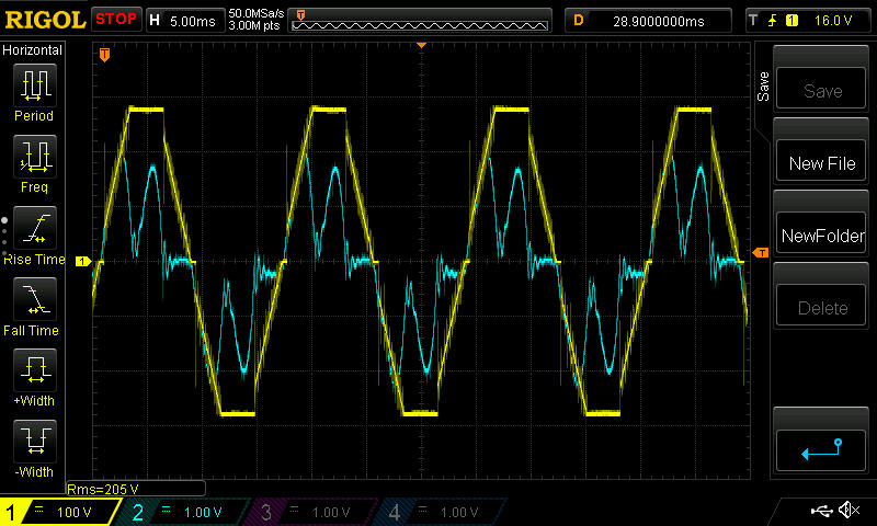
Some VFD manufacturers provide rated current and saturation current as rms values in the datasheets of their line reactors. VFD input current is, however, not a clean sinusoid, but rather a series of current pulses (4 per cycle with 3-phase input, 2 per cycle with 1-phase input) with peaks that can range in the 2-4x the rms value. If the current peak exceeds the peak value of the manufacturer given rms saturation current, what happens? (For example, say the current peak reaches 105A but the saturation current is 60 Arms). As I understand it, a saturated inductor basically turns into a short circuit, how does this manifest in the current/voltage waveforms when viewing them on an oscilloscope?

Secondary to this, assuming that a 3-phase reactor is used (3 coils), but only a 1-phase input (2-outer coils are used), is there any change in rated saturation current (i.e. can the reactor handle more current before going into saturation), or does this not matter?
 
Replies continue below

Recommended for you

For a single phase reactor current in excess of saturation will be limited by the air core impedance of the reactor.

--------------------
Ohm's law
Not just a good idea;
It's the LAW!
 
The saturation current is proportional to frequency, so reactors can probably withstand significant amounts of harmonic content in distorted waveforms without saturating.

I assume it would very difficult to distinguish the effects of reactor saturation on a highly distorted waveform. If you measured the voltage across a reactor going into saturation due to just the 60 Hz component, I think the last portion of each half cycle the waveform would be a flatish line such as:

8-Figure13-1_oty1gh.png
 
Thank you for the responses.

I see. So there is still some reactance, but suddenly a small fraction of the original reactance once the current hits a certain magnitude?

The waveform images are very useful, and that makes sense. I do have a 3-phase line reactor on a pump in an R&D lab where the voltage between any two phases at the reactor output (but not across the reactor) looks like a triangle wave on rise and fall, and a square wave at the top and bottom (see image). I was curious about what causes this and if this is an indicator of saturation.
Reactor_Output_yeoaov.jpg
 
What kind of power supply is used here? And what overvoltage protection devices?
Seems there is voltage limiting (clipping) not reactor saturation.
 
The output voltage of a reactor, or any other VFD filter, won't be a sine wave. I'm not sure if what you have is correct, but I would suspect it's fine. VFD reactor manufacturers know the load, so the reactor can be designed to match.
 
Status
Not open for further replies.
Back
Top