Par 40 Motor Options Config 1001 1000 1111 x111
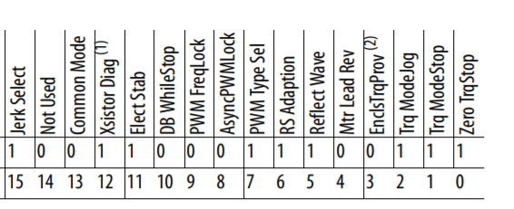
Bit 0 “Zero TrqStop” – Configures stopped condition when in torque mode. [highlight #8AE234]1 = wait for zero torque before shutting off drive output.[/highlight]
Bit 1 “Trq ModeStop” – Configures stopping behavior when in torque mode.[highlight #8AE234] 1 = switch to speed mode[/highlight]
Bit 2 “Trq ModeJog” – Configures jogging behavior when in torque mode. [highlight #8AE234]1 = switch to speed mode[/highlight]
[highlight #EF2929]
Bit 3 “EnclsTrqProv” – Enables encoderless mode when using the torque prove function.[/highlight]
Bit 4 “Mtr Lead Rev” – Reverses the phase rotation of the applied voltage, effectively reversing the motor leads. [highlight #8AE234]1 = Reversed[/highlight]
Bit 5 “Reflect Wave” – Enables reflected wave voltage protection for long motor cables.[highlight #8AE234] 1 = Enabled[/highlight]
Bit 6 “RS Adaption” – Adapts for changes in motor stator resistance due to motor temperature. Active only in FV motor control mode with feedback.[highlight #8AE234] 1 = Enabled[/highlight]
Bit 7 “PWM Type Sel” – Configures 3 Phase / 2 Phase switching of the power devices. [highlight #8AE234]1 = Full time 3 phase modulation (no switchover)[/highlight]
Bit 8 “AsyncPWMLock” – Configures Synchronous / Asynchronous switching of the power devices. 0 = Automatically changes between synchronous and
asynchronous.
Bit 9 “PWM FreqLock” – Configures switching frequency of the power devices while in FV motor control mode without feedback. 0 = switching frequency
automatically reduces to 2 kHz at low speeds (best performance)
Bit 10 “DB WhileStop” – Enables operation of the dynamic brake transistor while the drive is stopped. 0 = Disabled
Bit 11 “Elect Stab” – Enables stability control for Sensorless Vector and V/Hz motor control modes. [highlight #8AE234] 1 = Enabled[/highlight]
Bit 12 “Xsistor Diag” – Enables power transistor diagnostic test at each start command. Recommended to set to Disabled if an output filter is installed with the drive. Refer to publication PFLEX-AT002 for additional information. [highlight #8AE234] 1 = Enabled[/highlight]
Bit 13 “Common Mode” – Enables the common mode reduction feature. See Parameter 41, Common Mode Type, for common mode type selection.
[highlight #EF2929]Bit 14[/highlight]
Bit 15 “Jerk Select” – Limits the rate of change to the velocity reference for improved current limiting. This setting applies only to Sensorless Vector and V/Hz motor control modes. [highlight #8AE234]1 = Enabled (0.0 second ramp time prevented)[/highlight]
You might want to look at bit 12 and bit 15.
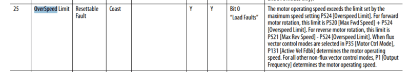
bit 15 is what waross was taking about earlier, it smoots the speed in the corners when going from acc/deacc to continues speed this makes it run without "pulls and jerks" which can create "folloing errors / overspeed faults"
BR A
“Logic will get you from A to Z; imagination will get you everywhere.“
Albert Einstein
![[pc2]](/data/assets/smilies/pc2.gif "[pc2] [pc2]")
![[thumbsup2]](/data/assets/smilies/thumbsup2.gif "[thumbsup2] [thumbsup2]")
![[ponder]](/data/assets/smilies/ponder.gif "[ponder] [ponder]")