Eng-Tips is the largest engineering community on the Internet

Intelligent Work Forums for Engineering Professionals

VIBRATION TEST FIXTURE.

Status
Not open for further replies.

srini1785

Electrical
Apr 5, 2021
34
0
0
IN
Hello,

I am aware that there are threads which discuss this topic but there are some specifics which i wanted to share in this thread.

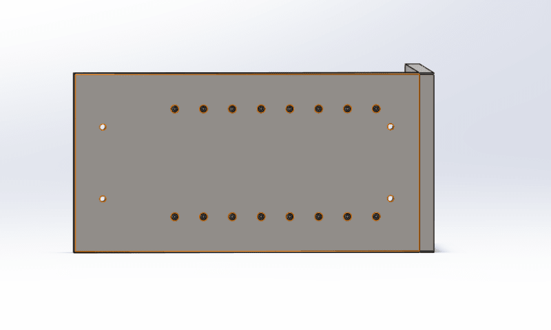
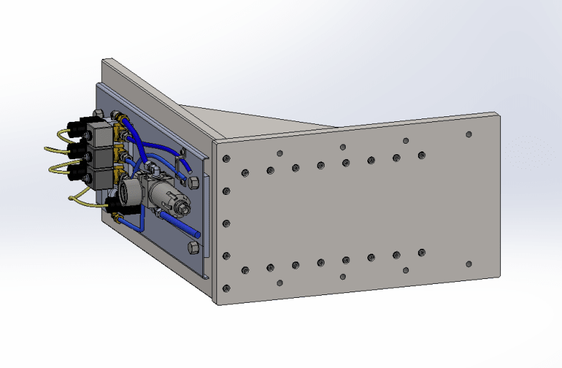
1. Specimen : Pneumatic Panel 448x187mm with 3mm R4 bend. Aluminium, 3mm sheet thickness.
2. Test Standard : IEC 61373 HL2
2. Weight 3Kgs (approx.)
4. Orientation : Vertical


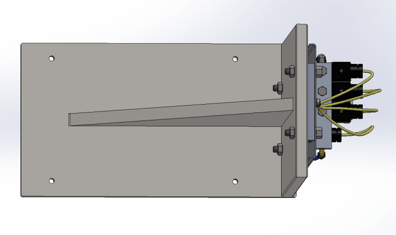
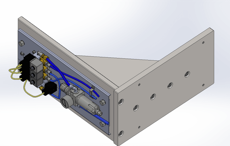
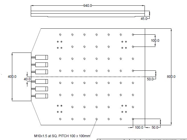
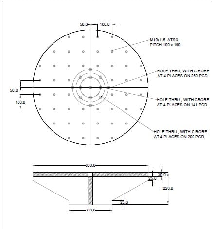
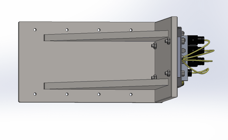
I am thinking of making the fixture out of MS (20mm) thick wedge shape. A simple diagram is attached.

Fixture_x9pdgj.jpg


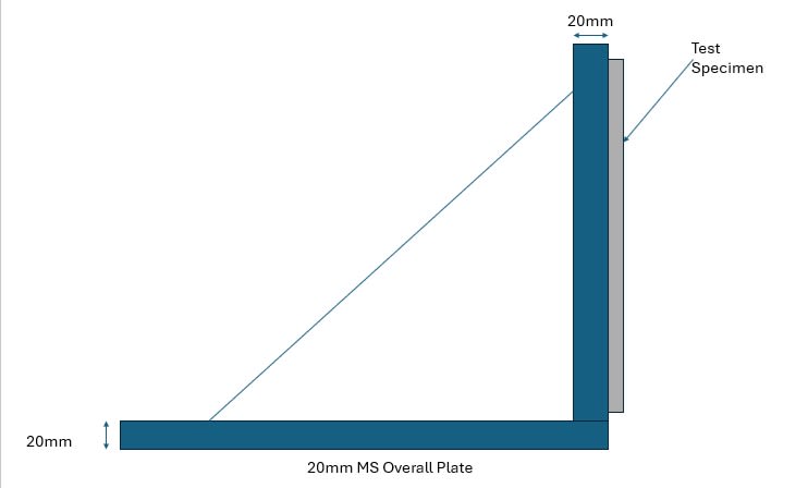
I was told to design something stiff which would not vibrate with the same freq as the panel. So i did it this way. This is probably the first and last fixture that i will ever design.
 
Replies continue below

Recommended for you

add a web/stiffener between the two plates (or is that what the diagonal line represents ?)
the horizontal plate should attach to the "rest of the world" (the loading apparatus ?) with 4 bolts in a square pattern.

"Hoffen wir mal, dass alles gut geht !"
General Paulus, Nov 1942, outside Stalingrad after the launch of Operation Uranus.
 
It's overkill, but steel is cheap.

How do you plan to connect the three pieces of the fixture together?

Fillet welds will probably (Almost certainly) not survive the test.

Generally, full-penetration welds are good for vibration fixtures but here your 20 mm plate thickness becomes a problem.

Screwed might survive. More screws of small diameter would be better than fewer screws of big diameter. Replace them after each axis.

The holes that mount the panel to the train are poorly placed relative to where the valves and regulator mount to the panel. That will cause a lot of bending in the axis perpendicular to the front of the panel. Shorten the load path between the components and the train.
 
Only kind of related - you'd generally want to mount the specimen the same as real life. Looks like yours may be glued on? That will change the frequency response.
 
Concur with Mint.

For what it's worth, as a young engineer I was taught Ol' Skool automotive industry fixture design philosophy by our Resident Gray Haired Shop Wizard:
[ul]
[li]steel is cheap, so use plenty of it (extra mass is your friend)[/li]
[li]use thick gussets and burn 'em in (full length deep welds for rigidity)[/li]
[li]whack test it: bang the assembly with a mallet and observe natural frequency response [wink]:[/li]
[li]if it bongs then not OK[/li]
[li]if it thunks then nearly OK[/li]
[li]if it thuds, then probably OK[/li]​
[/ul]

TygerDawg
Blue Technik LLC
Manufacturing Engineering Consulting
 
"surely" we can be just a little better than that these days ... the test environment will have a maximum frequency, the test fixture should be "rigid" to some higher frequency (double ?).

"Hoffen wir mal, dass alles gut geht !"
General Paulus, Nov 1942, outside Stalingrad after the launch of Operation Uranus.
 
Is the vib test in-house or outside?
Check the mounting. Some outside vib companies are limited to size.
I never used any type of welding, they can crack. This is from outside vib companies experience.
Vib fixtures that I have made in the past were 1" plates, usually magnesium works well with high frequencies. A good tool steel works too on some.

Chris, CSWP
SolidWorks
ctophers home
 
Thank all members for your suggestions. Some clarifications.

1. The General Design is as given below.
image_2024_06_27T08_25_28_032Z_dbuax2.png


image_2024_06_27T08_24_53_569Z_nnpl2l.png


2. The vibration test is done through an external lab and the dimensions of the bench are as follows.
XY Table
XY_Table_h7y3qn.jpg

Z Table
Z_table_y8aw3g.jpg


3. I've dropped the idea of welded plates based on your recommendations. I'll probably use 4-5 M10 nuts to fix the three plates in place. I've given a 5mm groove so as to locate the plates.

4. I'm a tad reluctant to let go of the 20mm plate thickness.

5. The overall weight of the fixture is around 49Kgs.

6. Carbon steel is what i have chosen.

7. All nuts are fastened using Loctite (243).
 
The image doesn't look like countersunk screws, but maybe they are.
My suggestion is don't use countersunk on a vib fixture. The heads may shear off.
Also, slotted head may strip.
Maybe use socket head cap.

Chris, CSWP
SolidWorks
ctophers home
 
We've tended to avoid bolted fixtures, mainly because the maintenance of such requires constant verification of bolt tightness. We've used fillet welds on similar fixtures and have never had a problem, although most of our fixtures are aluminum.

TTFN (ta ta for now)
I can do absolutely anything. I'm an expert! faq731-376 forum1529 Entire Forum list
 
Do not use countersunk screws and holes.
Do not use slotted head screws. Use regular hex-head with a counter-bore sized for a socket.
Use more, smaller screws. Maybe M6. Smaller screws will stretch more and be more resistant to loosening.
Use more screws to connect the two rectangular plates.
Use more screws to attach the fixture to the shaker table.
Follow Greg's advice about two gussets and torsional mode.
 
Based on the Z table drawing I guess that the shakers is an Unholtz-Dickie H560B-12. If so, this fixture + equipment is no where near its capacity. But always good to double check with the lab.

Yes, from first principles it would be "better" to mount the IUT on the other side. But the IUT is 3 Kg vs the fixture at about 50 Kg, so in practice it's not likely to make much difference.
 
srini1785 said:
Yes, countersunk screws
Those are maybe the worst kind of screws you could've chosen.

Conical head of the countersunk screws aligns itself exactly to the conical hole. But if the threaded hole on the mating part is not in the exactly the correct position (which it never is, because real world is not ideal), the screw will never optimally sit in its hole. Countersink works better if there's a through hole on the mating part and the nut on the other side as opposed to a threaded hole.
Also, slotted screwdriver head is one of the worst kinds, too. Can't be torqued properly and is prone to stripping. It's also much more finicky to work with, so it's a good way to get assembly technicians to hate you.

Both of these increase the chance of loosening.

Always prioritize using either hex head bolts or SHCS (socket head cap screw) for general applications, and use other types only if those are unsuitable for whatever reason.
 
Few points to clarify now. The design is changed. We've now incorporated two gussets, M6 nuts (Cheese head with Allen nuts) 8 nos for each surface, more number of holes for mounting on the table. Further, the thread will be only on one mating part with the other having a through hole and a counter sunk.

The vertical side for the panel.
image_2024_06_28T06_05_03_076Z_fgngwm.png

Mounting side on the table.
image_2024_06_28T06_03_00_178Z_u9qklr.png

Plan view
image_2024_06_28T06_03_30_288Z_afsmvn.png

The bolts
slotted-cheese-head-screw_yqrl2c.jpg


I'm not sure if we need to use aluminium or fillet weld the MS plates after bolting the pieces to gather. Further, I am advised by the lab that 50 Kgs should not be a problem for this table so we are within limits.
 
Good job!

I think that will be fine. I'm looking at a picture of a bolted aluminum fixture used to test a similar size and weight component to the same IEC 61373 requirement.

Similar to your first design, it had only one gusset.

That fixture survived, although it was sort of springy, forcing a bunch of post processing to get meaningful response signals.

Yours will be much stiffer.

Let us know how it goes.
 
Status
Not open for further replies.
Back
Top