Continue to Site

Eng-Tips is the largest engineering community on the Internet

Intelligent Work Forums for Engineering Professionals

  • Congratulations KootK on being selected by the Eng-Tips community for having the most helpful posts in the forums last week. Way to Go!

Visualization of MMB for a clocking datum feature

Status
Not open for further replies.

Burunduk

Mechanical
May 2, 2019
2,339
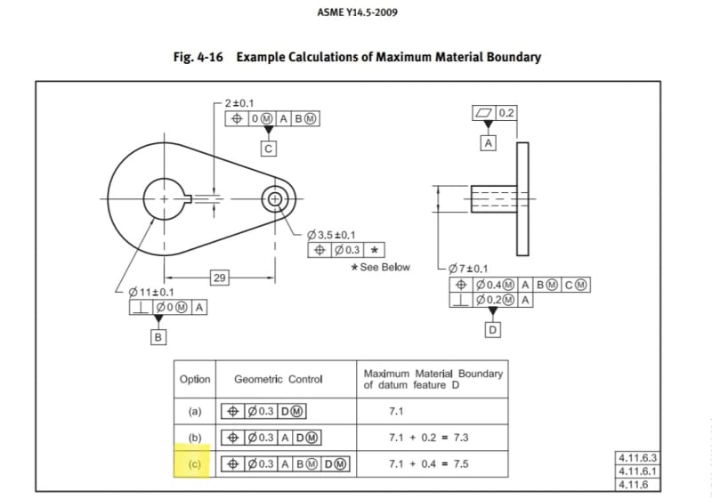
As promised on another thread, I made two CAD sketches addressing figure 4-16 in the Y14.5-2009 standard, option (c) (renumbered 7-22 in the 2018 edition). It is intended to illustrate the shape and size of the MMB of datum feature D, representing the dimensions of the required datum feature simulator. One of the sketches shows the correct interpretation according to agreed upon terms and conventions, and the other one is an approximation of a different solution discussed in this forum in the past, which is based on a wrong interpretation that violates the rules of ASME Y14.5, unless it follows an explicit drawing requirement.

The problem at hand, calculation of the MMB for option (c):
Screenshot_20220510-190904_Drive_vrxdnu.jpg


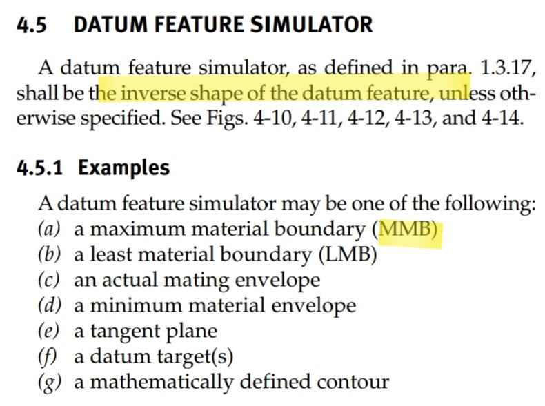
The most common application for the MMB determination is setting the size of a "datum feature simulator", the theoretical type of which is called both prior to and following the 2009 edition of the standard, the "true geometric counterpart", an important element of datum reference frame establishment:
Screenshot_20220510-200028_Drive_tmpgdz.jpg


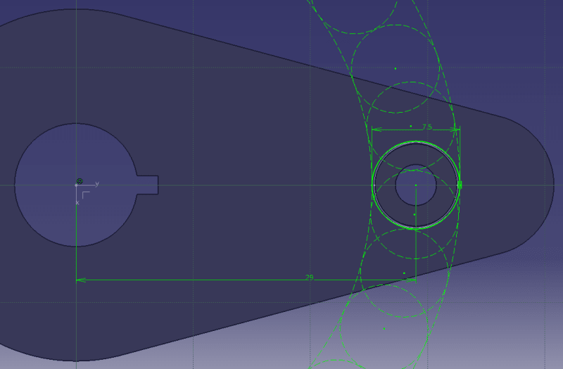
The correct solution:
An MMB boundary resulting from

1. MMC size of datum feature D - 7.1 (also encompasses form variation per rule #1)

2. The allowed variation in location and orientation of datum feature D relative to datum references A as a primary and B(M) as secondary, as derived from the position tolerance applied to datum feature D with reference to datum features A, B(M), and C(M), which also encompasses the possible perpendicularity variation. This is part of an analysis that follows the standardized conventions and does not differentiate between tangential and radial direction variations related to the circle of the possible true positions that would be formed without the clocking datum reference, because it is based on a cylindrical VC (virtual condition) calculated from the position tolerance applied to datum feature D, which can be viewed as applying around any true position on the periphery of the 29 mm radius circle centered at datum B. This tolerance value is 0.4.

The resulting cylindrical boundary is of 7.1+0.4=7.5 diameter, shown in the below sketch as a circle around the nominal datum feature D, and at multiple additional possible locations (dashed) on an arc radius of 29 mm originating at datum axis B. The additional locations are there because the simulator for datum feature D is not clocked by anything around datum B, when establishing the A, B(M), D(M) datum reference frame. From obvious reasons, the useful additional locations for a compatible part will be much closer to the nominal location of datum feature D in a fully constrained datum reference frame and not as shown here for illustration only. This solution is in accordance with the requirement that the datum feature simulator is of the inverse shape of the datum feature.
correct_solution_l7uxcr.png


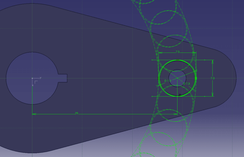
Now to the incorrect solution:
This solution separates the allowed variation values according to the constraints in the radial and tangential directions related to an arc of a 29 mm radius originating at datum B.

The calculation for the "MMB" combines two different boundaries into one:

1. The virtual condition for the perpendicularity tolerance that includes the MMC size (that also encompasses form variations per rule #1) and results in 7.1+0.2=7.3. This dimension represents the size of what is mistaken for the MMB in the tangential direction, as the datum feature simulator for D is not clocked during the simulation. It can follow the actual as produced pin along the 29 mm radius arc, so the tangential size supposedly needs to only account for perpendicularity variation relative to A and the MMC size.

2. A boundary that encompasses the MMC size and the location variation of datum feature D relative to datum references A as primary and B(M) as secondary as described above in the first solution, but this time considered in the radial direction only, because the position tolerance does not limit translation in the tangential direction once the tertiary datum reference is no longer considered. The tolerance value of position, 0.4 is added to the MMC of 7.1 and that gives 7.5 for the radial direction.

The shape and size of this combined boundry is roughly estimated to be an oblong of 7.3X7.5 for the illustration purpose, constructed by offsetting one 7.3 diameter boundary from the pin's true position radius all the way to the positive radial direction and another one all the way to the negative radial direction within the limits set by the 7.5 boundary. A more thorough analysis will thicken the semi-oblong slightly due to additional possible translations of the geometry, but not in the pure radial and tangential directions.
incorrect_solution_ptmz1h.png


This (second) solution is incompatible with the dimensioning and tolerancing standards, as it ignores the requirement that the datum feature simulator is to be of the inverse shape of the datum feature, and the general standardized practice of considering the locational tolerance size and shape to be generally symmetric in all directions around the true position independently of whether the constraints in the relevant displacement directions are full (such as when the X and Y axes defining the tolerance zone location are locked in rotation about Z) or partial (such as when the X and Y axes defining the tolerance zone location can rotate about Z). An application of an MMB datum feature simulator according to this solution will impose an over-restrictive requirement due to reduced datum shift in the radial direction, and may cause increased scrap.
 
Replies continue below

Recommended for you

Rules + wall of text + indistinct diagram. Perfect.

" the requirement that the datum feature simulator is to be of the inverse shape of the datum feature"

Exactly the same argument, over and over. But not establishing the shape required to minimally envelope the feature.

I don't see any shape showing the tilted condition of the pin. As I wrote before - you need to be trained to do that in a CAD system.
 
Try with a position tolerance of 4 on the same nominal feature and the perpendicularity of zero and model, individually, the entire range of acceptable results for the location of the pin. We don't need to see the hole; you can zoom in closer.
 
3D,
If you think that showing the tilted condition of the pin graphically and other improvements in visualization can benefit the discussion, you are welcome to contribute.
 
I did. Already. You didn't like it before and you won't like it now. The control of the rotation is by the width in the tangential direction which is constrained by the size, 2018 - straightness, and perpendicularity. The radial dimension and the tolerance that controls that aren't important in establishing that control.
 
I'm sorry that my CAD diagrams are not to your liking, but I don't recall yours showing the tilt of the pin, as you require, either.

3D said:
The control of the rotation is by the width in the tangential direction which is constrained by the size, 2018 - straightness, and perpendicularity. The radial dimension and the tolerance that controls that aren't important in establishing that control.

Yes, it's pretty much in line with my description above, of the incorrect interpretation. It could have been correct if it was based on a different set of rules and definitions than the one from which the figure and the calculation that you consider to be wrong originates.
 
The software showed the tilted axes. You didn't like it.

I can see your confusion. The radial variation must, for you, control the tangential motion. Which is why you will refuse to depict a larger radial variation to make the absurdity of that interpretation clear.
 

Tilted axes are usually shown as slanted lines, and not at a view from the top.
All this matters little.
What matters is the substance.

"The radial variation must, for you, control the tangential motion."
It's not must, for me. But it is a result of the definitions. Whether it is for tolerance zones or boundaries, the differentiation between "radial" and "tangential" is rare, and irrelevant to the figure. The calculation is consistent with the concepts it is based on.
 
The point is to determine the amount the width of the feature is affected, so the projection of the tilted axis is enough. That's what you would argue if asked to explain it.

When you say "it is a result of the definitions" I'm impressed that you have never dealt with resolving vectors into orthogonal parts.

Of course it is rare - that's why the figure creator got it wrong.

Still, no examination of a much larger position tolerance zone? I imagine you already know what that will look like and don't care to be caught out on it.
 

3DDave said:
When you say "it is a result of the definitions" I'm impressed that you have never dealt with resolving vectors into orthogonal parts.

It has nothing to do with resolving vectors. What I've been saying is that it has to do with the definition of what is being calculated. If "X" is defined as "X" it makes no sense to claim that the calculation of "X" has an error because the result of the calculation is not "Y".
It would only be an error if they attempted to calculate "Y" and got "X".

Expecting users to make software simulations to determine the shape of a datum feature simulator for every case is not workable. A contracting oblong slot for an RMB pin is not workable. A datum feature simulator of the inverse shape of the datum feature is consistent with all the related definitions and workable. That is why the standard doesn't deal with the "Y" in question the way you expect it to deal with.

If "X" gives more datum shift than a certain application should tolerate a competent designer will be aware of it, adjust tolerance values, change the material condition and material boundary specifications or use methods such as bidirectional positional tolerancing for the datum feature, resulting in two different boundaries to account for different radial and tangential variations.
 
They did adjust it - they added perpendicularity. That narrowed it. It could be the best way to do so as it may solve other problems.

You don't have a clue as to how much math needs to be done for anything but the most trivial cases. I'll tell you a secret - you don't even know the fundamental theory of what MMB is based on - that is, only if the datum reference frames of the individual parts that were used to accept the mating features are perfectly aligned between the parts are all the clearance calculations valid. Only if they are aligned, for drawing compliant parts, are all the bolts guaranteed to fit through all the holes. There may be an infinite number of solutions where they may be slightly off and still fit or there may be just the one. See figure 4-26. There should be on every assembly drawing assembly dimensions and tolerances given to precisely locate the parts to allow that assembly, but usually the parts are used as an analog computer to perform all the math and the fasteners and parts wiggled to locate a solution by trial and error.

Now - consider that math when one of those alternate solutions is selected - how much misalignment is allowed, like, how much does the base of that part in Figure 4-26 rotate? Note that it may be forced to rotate to line up those fittings. How far to the side do the corners move and will that interfere with neighboring parts? If you think this little pin problem is overwhelming, never try anything where alignment actually matters.

For RMB assemblies/interfaces - you should calculate the strains and stresses for installation.

Can two perpendicular surfaces be mated to two other perpendicular surfaces? Not if the variation between them is so high that to close the gaps requires more strength than the assemblers can apply to push them into position. How much math is used in strain and stress calculations? It's a surprise but pushing a 10 inch aluminum angle with .75 thick flanges when they are out 0.10 inch isn't as easy as it appears.


The geometric math is what the VSA company formed to do - it's a shame that it is expensive and people think "I took a class, have a book, what's there to know? Add diameters and done." Worse, to use software like that requires knowing what to look for. It's similar to why FEA companies exist to perform stress and vibration analysis. Just because there are those unable to do the math doesn't mean they should be given bad information.

In fact, that contracting oblong is exactly what an RMB is required to do for an irregular feature so that is by definition workable.

Ordinarily this odd outcome would not occur, but they changed the reference frame from the one the feature was defined in to a different one. Perhaps the committee should not be creating situations they cannot evaluate correctly. I think this was the only one and then they trippled it.

And people such as yourself think that they can define away the actual result of the tolerance choices that establish those feature in the first place because they point and say "That's how they did it."

Notice I think (a) and (c) are fine - they did not change to a new frame of reference that was not involved to define the feature. That's why when the question was asked I thought it was a badly formed training question; but it makes sense that badly formed example like this is in there as many of the committee members have training services and figured that the form allowed in one datum reference frame would be identical to that in another one. they don't realize that it's not.

Here's the question I had before - what is the limit for B in [A|D|B]? Is that still involving only the perpendicularity tolerance on datum feature B? Feel free to overlay a few hundred compliant variations to see what shape will close in the hole. Since the basic dimension is 29 ('2009) and there is not position tolerance does the center distance change?
 
Fitting requirements between mating parts is why we have worst case boundaries with developed definitions such as VC and MMB to work by. You make sure the parts are going to fit by using them.
You seldom need to know the clearance in every direction for every feature for every possible assembly solution given the design dimensions and tolerances and the actual values as measured.

If you do an alignment analysis for a part dimensioned and toleranced per Y14.5, and consider in your analysis that parts will be inspected with gages made according to a simulation that separates between radial and axial types of variation and combines them into special shape MMBs and datum feature simulators, because you think that this is the correct, default, interpretation, then you will eventually end up with approved parts that do not align according to your design intent, because what you mean to specify - what you base your analysis on, is different from the acceptable interpretation of your specification. If you are aware of the rules that govern the acceptable interpretation, such as the ones that lead to the conclusion that the inverse shape of the datum feature sets the shape of the datum feature simulator while the size of it is set by all the relevant tolerances, you can better predict the possible results of your specification and adjust your drawing requirements accordingly. But If you don't care that your design can fail, you can keep being convinced that the problem is only in the numbers calculated in figure 4-16, and not with your understanding of the definitions which the calculation is based on.

I suppose that you mean that the question that you were asking in the past was about the MMB of datum feature B as tertiary, if you changed the order of datum references in the '09 figure option (c) to A, D(M), B(M).
Why do you even suggest the option that it could be "involving only the perpendicularity tolerance on datum feature B"?
If a control with such references was needed, it would make sense to control datum feature B for location relative to A,D(M). But as it is, there needs to be some analysis that accounts for the variations, including in location, of datum feature B given the specified tolerances when constraints are applied through datum feature A as primary and datum feature D at MMB as secondary.
Obviously you shouldn't "overlay a few hundred compliant variations to see what shape will close in the hole", that's why we have worst case boundaries.

First rely on the control on datum feature D referencing A as primary, B(M) as secondary and determine a part configuration in which all datum features are within their tolerances but have the maximum mutual dislocation, using all the potential datum shift and position tolerance for translation from basic.
Take a piece of paper and start sketching a gage with a face to mate with datum feature A, a 10.9 MMB diameter pin to constrain datum feature B to, and a 7.5 diameter virtual condition hole for the pin according to the position tolerance applied to it. Adjacent to that gage draw an actual part with 11.1 diameter (LMC) datum feature B hole and near-zero perpendicularity, and a 6.9 diameter (LMC) pin, such as the pin and the hole are as far apart as the gage allows. You will find that this allows hole-to-pin axis separation to increase to 29.4.

Then considering the A primary, D(M) secondary, B(M) tertiary datum reference frame you are asking about, draw the same part you obtained in the first step separately. Adjacent to it draw the new gage, in which the hole diameter for the datum feature D pin is 7.3 according to the perpendicularity virtual condition, and a pin to mate with datum feature B located 29 mm from the axis of the 7.3 mm hole. The interface with the part should be again such that it limits the axis separation in the part to the maximum of 29.4. You will find that in order to make the gage accept the part, the axis to axis distance resulting from the shift between the MMB boundary of datum feature simulator B and the axis of datum feature B needs to be 0.2, and the MMB for B (gage) radius should be the result of the LMC of datum feature B minus the 0.2 axis to axis shift distance, giving a 5.35 radius and a 10.7 diameter.

For checking yourself, repeat the same steps for a case with the minimum axis separation between the datum features. You are expected to obtain 28.6 axis distance between datum features B and D and again an MMB boundary diameter for datum feature B that equals 10.7.

If you have a difficulty to derive that from a hand sketch, ask your "CAD guy" to make you a diagram.
 
So, what I gather from that wall of text is you aren't particularly good at geometry.

"then you will eventually end up with approved parts that do not align according to your design intent,"

You cannot predict how they align if you don't understand what variation is allowed. Making a worthless calculation based on a bad assumption from an incomplete rule isn't going to help. When that simulator clamps down that diameter you are calculating is larger than the width that feature will be constrained to. By overestimating the variability you will then be forced to an unnecessarily smaller tolerance - costing more. Don't let excess expense be a refuge.

"You shouldn't " is the opposite of how the Monte Carlo method of analysis works.

Your calculation shows only one dimension of the non-circular result which means that the side-to-side clearance variation will not match. You won't see that without the overlay. Being able to visualize these things is a valuable skill to have and you should learn to do it.


3DDave said:
You cannot predict how they align if you don't understand what variation is allowed

Exactly as I said. You will not know what variation is allowed because you will think they should use an oblong slot as a datum feature simulator, and you don't explicitly specify it on a drawing, but they will follow the rules anyway and use a round hole as the gage. Therefore you won't be able to predict how your parts align, despite your analysis.

The standard doesn't tell you not to do your analysis. It is just that your particular analysis is not within the scope of figure 4-16 or the concepts it is brought as an example of, so your numerous claims in this forum that the analysis in the figure is incorrect is like listening to a lecture about apples and then saying that lecturer was terrible because everything he told about oranges is wrong.

The MMB concept, just like the VC, considers the most common application in which the pin is going to mate with a hole in the mating part, hence the "inverse shape" rule. Datum simulation rules are intended to mimic the functional assembly. If the pin is going to mate with anything but a hole and you want to mimic that closely, you can apply the "otherwise specified" option and explicitly define whatever you want.

In an MMB application, the designer is not likely to care about equal maximum clearance in the radial and tangential directions. As I mentioned already, if the variation in each of these directions is important, the bidirectional positional tolerancing (like in figure 7-29) can be applied. Then the tolerance zone is not a cylinder and each direction is treated as a width. If a datum feature is toleranced that way, the simulator would be understood as two slots, each would correspond with the variation in the specific direction.
 
I think you get it - the standard is showing an incorrect result. That should not be the case. Applying rules from one frame of reference to another is complicated and they did it wrong.

It should be an example of why not to walk onto the highway where it is safe to be in a car - moving from one reference frame to another is complicated.

B said:
the designer is not likely to care about equal maximum clearance in the radial and tangential directions.

An analysis isn't supposed to depend on what the designer cares about. It should be what the designer will get.
 
There are cases where the analysis you promote will be needed, in most cases it won't.
The standard doesn't show an incorrect result for what it defines as an MMB. It generally considers the farthest the feature will reach towards the surrounding space under specific constraints of degrees of freedom and tolerances and applies it around the nominal feature symmetrically, even if it is not the most accurate representation of what happens when you take specific directions into consideration. However, it is useful for what it is.

The Y14.5 standard generalizes the directions of translation according to three mutually perpendicular planes, it does not differentiate between positive and negative directions of the X, Y and Z axes although some figures show them. Under these conditions, it can't be expected that "tangential" and "radial" are treated separately for establishment of boundaries.

You think of a different thing as the MMB.
As I said, apples and oranges.
 
Oh - so that control of w about what would conventionally be the z axis is not affected differently than the radial direction?

Perhaps it is unclear just what tangential means in establishing a rotational constraint. How can I help you in knowing that?
 
Rotation about Z is unconstrained for datum feature simulator D during simulation by the A and B(M) references, and it's not part of the discussion. A tangential translation is still a translation, and it is limited by the position tolerance, acting in all directions around the true position.
 
The position tolerance is only restricted along the arc by a reference to datum feature C.
 
3DDave said:
The position tolerance is only restricted along the arc by a referencing to datum feature C.
According to the practices covered by Y14.5, without the reference to C, it is considered that any point on the arc can be viewed as the true position.
Around the true position you get a cylindrical tolerance zone, and the cylindrical VC that corresponds with it.
The reference to C only locks the rotation of these cylinders about B.
When the pin is considered as a tertiary datum feature in a datum reference frame that references A as primary and B(M) as secondary, the constraint of rotation about B is removed, and the VC of datum feature D relative to only A primary, B(M) secondary, that as mentioned can rotate about B, becomes the MMB. These are the apples that are used to provide workable solutions for datum simulation, and correspond with functional requirements when the pin is mated to a hole. You prefer the oranges that can be used for analyzing the clearance, design of non-cylindrical mating part, and specifying special requirements on a drawing that override datum simulation defaults. The calculation in the figure is not erroneous.
 
Status
Not open for further replies.

Part and Inventory Search

Sponsor