Burunduk
Mechanical
- May 2, 2019
- 2,580
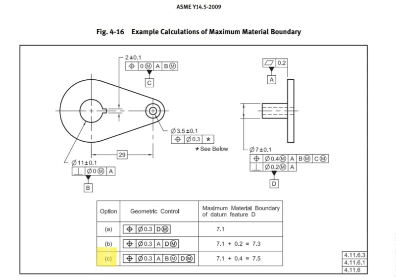
As promised on another thread, I made two CAD sketches addressing figure 4-16 in the Y14.5-2009 standard, option (c) (renumbered 7-22 in the 2018 edition). It is intended to illustrate the shape and size of the MMB of datum feature D, representing the dimensions of the required datum feature simulator. One of the sketches shows the correct interpretation according to agreed upon terms and conventions, and the other one is an approximation of a different solution discussed in this forum in the past, which is based on a wrong interpretation that violates the rules of ASME Y14.5, unless it follows an explicit drawing requirement.
The problem at hand, calculation of the MMB for option (c):

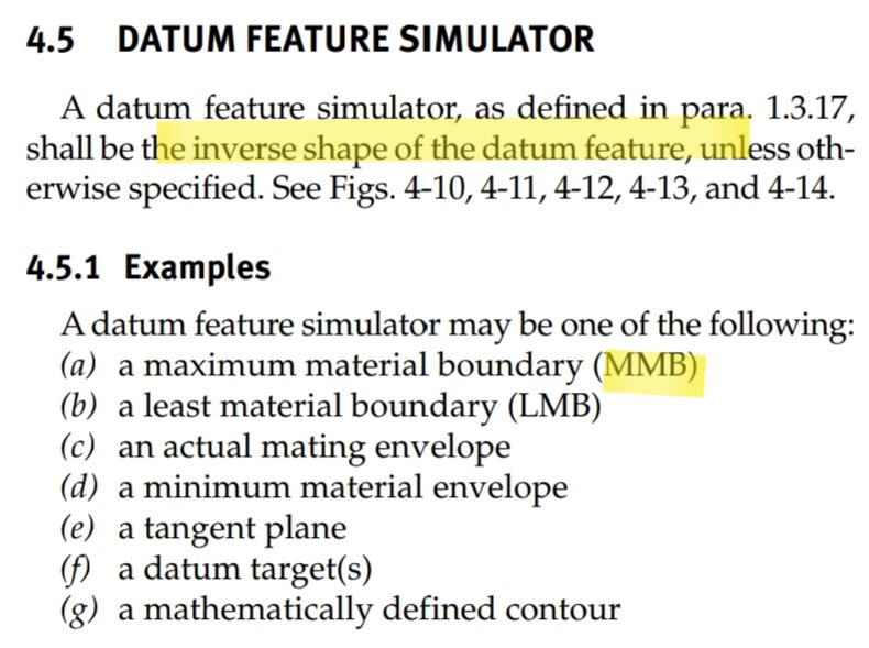
The most common application for the MMB determination is setting the size of a "datum feature simulator", the theoretical type of which is called both prior to and following the 2009 edition of the standard, the "true geometric counterpart", an important element of datum reference frame establishment:

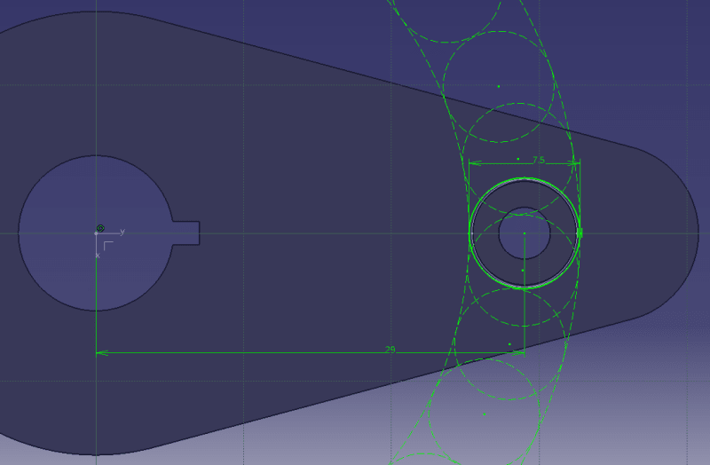
The correct solution:
An MMB boundary resulting from
1. MMC size of datum feature D - 7.1 (also encompasses form variation per rule #1)
2. The allowed variation in location and orientation of datum feature D relative to datum references A as a primary and B(M) as secondary, as derived from the position tolerance applied to datum feature D with reference to datum features A, B(M), and C(M), which also encompasses the possible perpendicularity variation. This is part of an analysis that follows the standardized conventions and does not differentiate between tangential and radial direction variations related to the circle of the possible true positions that would be formed without the clocking datum reference, because it is based on a cylindrical VC (virtual condition) calculated from the position tolerance applied to datum feature D, which can be viewed as applying around any true position on the periphery of the 29 mm radius circle centered at datum B. This tolerance value is 0.4.
The resulting cylindrical boundary is of 7.1+0.4=7.5 diameter, shown in the below sketch as a circle around the nominal datum feature D, and at multiple additional possible locations (dashed) on an arc radius of 29 mm originating at datum axis B. The additional locations are there because the simulator for datum feature D is not clocked by anything around datum B, when establishing the A, B(M), D(M) datum reference frame. From obvious reasons, the useful additional locations for a compatible part will be much closer to the nominal location of datum feature D in a fully constrained datum reference frame and not as shown here for illustration only. This solution is in accordance with the requirement that the datum feature simulator is of the inverse shape of the datum feature.

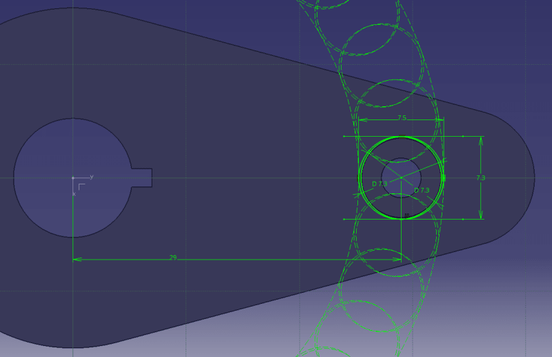
Now to the incorrect solution:
This solution separates the allowed variation values according to the constraints in the radial and tangential directions related to an arc of a 29 mm radius originating at datum B.
The calculation for the "MMB" combines two different boundaries into one:
1. The virtual condition for the perpendicularity tolerance that includes the MMC size (that also encompasses form variations per rule #1) and results in 7.1+0.2=7.3. This dimension represents the size of what is mistaken for the MMB in the tangential direction, as the datum feature simulator for D is not clocked during the simulation. It can follow the actual as produced pin along the 29 mm radius arc, so the tangential size supposedly needs to only account for perpendicularity variation relative to A and the MMC size.
2. A boundary that encompasses the MMC size and the location variation of datum feature D relative to datum references A as primary and B(M) as secondary as described above in the first solution, but this time considered in the radial direction only, because the position tolerance does not limit translation in the tangential direction once the tertiary datum reference is no longer considered. The tolerance value of position, 0.4 is added to the MMC of 7.1 and that gives 7.5 for the radial direction.
The shape and size of this combined boundry is roughly estimated to be an oblong of 7.3X7.5 for the illustration purpose, constructed by offsetting one 7.3 diameter boundary from the pin's true position radius all the way to the positive radial direction and another one all the way to the negative radial direction within the limits set by the 7.5 boundary. A more thorough analysis will thicken the semi-oblong slightly due to additional possible translations of the geometry, but not in the pure radial and tangential directions.

This (second) solution is incompatible with the dimensioning and tolerancing standards, as it ignores the requirement that the datum feature simulator is to be of the inverse shape of the datum feature, and the general standardized practice of considering the locational tolerance size and shape to be generally symmetric in all directions around the true position independently of whether the constraints in the relevant displacement directions are full (such as when the X and Y axes defining the tolerance zone location are locked in rotation about Z) or partial (such as when the X and Y axes defining the tolerance zone location can rotate about Z). An application of an MMB datum feature simulator according to this solution will impose an over-restrictive requirement due to reduced datum shift in the radial direction, and may cause increased scrap.
The problem at hand, calculation of the MMB for option (c):

The most common application for the MMB determination is setting the size of a "datum feature simulator", the theoretical type of which is called both prior to and following the 2009 edition of the standard, the "true geometric counterpart", an important element of datum reference frame establishment:

The correct solution:
An MMB boundary resulting from
1. MMC size of datum feature D - 7.1 (also encompasses form variation per rule #1)
2. The allowed variation in location and orientation of datum feature D relative to datum references A as a primary and B(M) as secondary, as derived from the position tolerance applied to datum feature D with reference to datum features A, B(M), and C(M), which also encompasses the possible perpendicularity variation. This is part of an analysis that follows the standardized conventions and does not differentiate between tangential and radial direction variations related to the circle of the possible true positions that would be formed without the clocking datum reference, because it is based on a cylindrical VC (virtual condition) calculated from the position tolerance applied to datum feature D, which can be viewed as applying around any true position on the periphery of the 29 mm radius circle centered at datum B. This tolerance value is 0.4.
The resulting cylindrical boundary is of 7.1+0.4=7.5 diameter, shown in the below sketch as a circle around the nominal datum feature D, and at multiple additional possible locations (dashed) on an arc radius of 29 mm originating at datum axis B. The additional locations are there because the simulator for datum feature D is not clocked by anything around datum B, when establishing the A, B(M), D(M) datum reference frame. From obvious reasons, the useful additional locations for a compatible part will be much closer to the nominal location of datum feature D in a fully constrained datum reference frame and not as shown here for illustration only. This solution is in accordance with the requirement that the datum feature simulator is of the inverse shape of the datum feature.

Now to the incorrect solution:
This solution separates the allowed variation values according to the constraints in the radial and tangential directions related to an arc of a 29 mm radius originating at datum B.
The calculation for the "MMB" combines two different boundaries into one:
1. The virtual condition for the perpendicularity tolerance that includes the MMC size (that also encompasses form variations per rule #1) and results in 7.1+0.2=7.3. This dimension represents the size of what is mistaken for the MMB in the tangential direction, as the datum feature simulator for D is not clocked during the simulation. It can follow the actual as produced pin along the 29 mm radius arc, so the tangential size supposedly needs to only account for perpendicularity variation relative to A and the MMC size.
2. A boundary that encompasses the MMC size and the location variation of datum feature D relative to datum references A as primary and B(M) as secondary as described above in the first solution, but this time considered in the radial direction only, because the position tolerance does not limit translation in the tangential direction once the tertiary datum reference is no longer considered. The tolerance value of position, 0.4 is added to the MMC of 7.1 and that gives 7.5 for the radial direction.
The shape and size of this combined boundry is roughly estimated to be an oblong of 7.3X7.5 for the illustration purpose, constructed by offsetting one 7.3 diameter boundary from the pin's true position radius all the way to the positive radial direction and another one all the way to the negative radial direction within the limits set by the 7.5 boundary. A more thorough analysis will thicken the semi-oblong slightly due to additional possible translations of the geometry, but not in the pure radial and tangential directions.

This (second) solution is incompatible with the dimensioning and tolerancing standards, as it ignores the requirement that the datum feature simulator is to be of the inverse shape of the datum feature, and the general standardized practice of considering the locational tolerance size and shape to be generally symmetric in all directions around the true position independently of whether the constraints in the relevant displacement directions are full (such as when the X and Y axes defining the tolerance zone location are locked in rotation about Z) or partial (such as when the X and Y axes defining the tolerance zone location can rotate about Z). An application of an MMB datum feature simulator according to this solution will impose an over-restrictive requirement due to reduced datum shift in the radial direction, and may cause increased scrap.
