Eng-Tips is the largest engineering community on the Internet

Intelligent Work Forums for Engineering Professionals

Voltage drop with current harmonics 1

Status
Not open for further replies.

hhhansen

Electrical
Jan 14, 2004
61
0
6
DK
Model_incl_harmonics_p9zz5d.jpg
Meas1_080319_hddxx5.jpg
Meas2_080319_ura88l.jpg


Hello
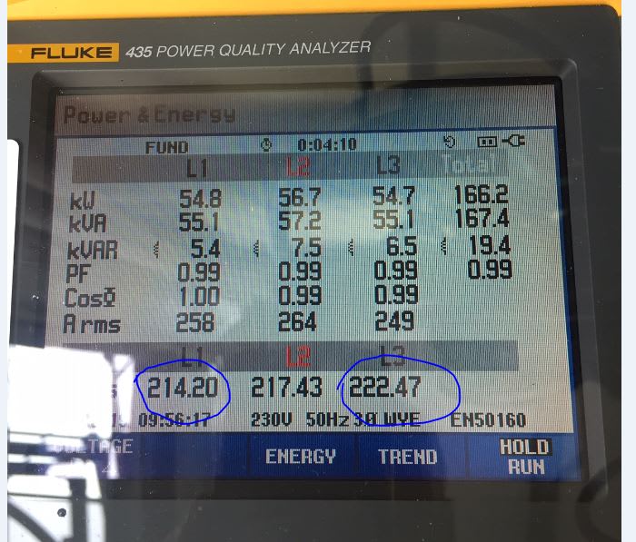
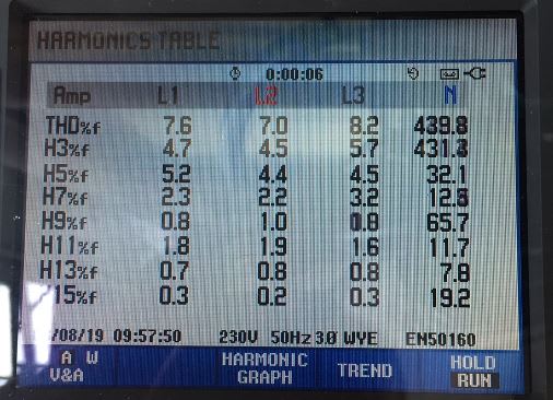
At a horticulture with a lot of LED growth lamps we have made some measurements. See Fluke pictures below. I am not able to explain why L1 is dropping to 214 V and L3 is 8 V higher and 222 V. The load are approximately the same, 55-56 kW and 6-7 kVAr. Also the harmonics does not vary much from each other in each line.
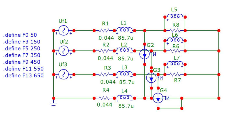
I have also set up a simulation model with harmonics inserted as sinusoidal current generators corresponding to measured harmonic currents. Loads are represented by R/L in parallel. Cable is (R1,L1...) with 240 mm2 Al, 350 m. Uf1,Uf2,Uf3 (in secondary substation) vary from each other less than 0,5 V and they are all represented by 230 Vrms.

Does anyone have any clues what may seem to be the problem. I a getting quite empty for more ideas. B.R. Hans-Henrik
 
Replies continue below

Recommended for you

Empty here, too.
Small difference, but irritating when everything looks OK. Did you check incoming MV (other side of the transformer)? It may be something that doesn't have anything with "your" load to do.

Gunnar Englund
--------------------------------------
Half full - Half empty? I don't mind. It's what in it that counts.
 
Capacitance between cables and their arrangement? Maybe, roll the phases and see if it follows?

Unequal distribution of load?

LED lights I believe will be constant current loads. Maybe, the cable runs to each set of LEDs isn't the same.

When you turn off all the loads, how balanced are the voltages?

Do you have some voltage developing on your neutral from slight unbalanced loads? These are 220 V voltages so I assume they are line to neutral voltages. Check the neutral current and the line to line voltages.

Why do you care? Is it causing problems?


------------------------------------------------------------------------------------------
If you can't explain it to a six year old, you don't understand it yourself.
 
Different types of lighting with different characteristic drivers?
eg: High bay lighting in one area vs office lighting in another area.

Bill
--------------------
"Why not the best?"
Jimmy Carter
 
Waroos certainly has a point regarding various lighting technologies. However since harmonics are measured this has sort of been taken into consideration within the simulation.
What about some sort of uneven distibuted capacitance tending to raise the voltage?
 
Not likely. The harmonics are just about equal. A 0.6% difference in THDu doesn't point that way.

Gunnar Englund
--------------------------------------
Half full - Half empty? I don't mind. It's what in it that counts.
 
So, the voltages are balanced without the load? You never actually said one way or the other.

What is the source, three pole top transformers from the utility distribution line? It could just be impedance differences in the transformers.

It could also be as simple as another close by customer putting an unbalanced load onto the utility system.

I'm doubting the harmonics have much of anything to do with it. That imbalance would likely exist with any kind of load.
 
Hansen says Denmark (or Norway). No "pot" transformers here. And no 4160 V either.

I'm for unbalance already at MV side, which usually is 6 or 11 kV for s rural grid. As Huty says: can you switch off the load for a quick check? If unbalance still there - then it isn't the load as such.

I wouldn't bother the least. That imbalance is well within any limits existing on this planet.

Gunnar Englund
--------------------------------------
Half full - Half empty? I don't mind. It's what in it that counts.
 
I should have also asked why the imbalance is a problem?

I would have expected the LED lamps to have switching power supply ballasts which keep the output constant even with variations on the input voltage.
 
The imbalance of 8 V is not neccessarily a problem, but Seen from an Engineering perspective it is unsatisfying not being able to explain this. The customer is complaining about a low voltage of only 214 V in L1 with High load whilst it is 222 V in L3. Tapping up the substation trafo is a Challenge because other clients shouldn’t experience excessive voltage at reduced load patterns e.g. at Night.
I have thought about a possibility of bad (High resistive) cabling assembly at one Line.
 
Status
Not open for further replies.
Back
Top