Continue to Site

Eng-Tips is the largest engineering community on the Internet

Intelligent Work Forums for Engineering Professionals

  • Congratulations IDS on being selected by the Eng-Tips community for having the most helpful posts in the forums last week. Way to Go!

Voltage regulator questions 5

Status
Not open for further replies.

itsmoked

Electrical
Feb 18, 2005
19,114
I have a 1/2MW Cummins generator regulator issue.

Keep in mind I have NO spec plate on the unit what-so-ever. The V12 turbo'd engine generator is 480VAC delta supplying a handful of rail cars in a seasonal (this season) application. It is not paralleled.

The existing regulator is a Basler Electric APR125-5 (giant potted brick) which is no longer available.

The replacement is a VR902 made by who-knows. ESI??
We're supposed to include a power transformer between two phases that supplies the power to the regulator for the regulator to use for the generator's excitation.

1) How do I size this thing? Since I have no measured or nameplate info on the generator's excitation range, have you got any suggestions on the VA rating? What I do know is the excitation is based on 125Vdc and the 'expired' regulator was rated 5A 50/60Hz. Are we talking a 750VA 480:120V transformer?

2) We need to provide an (overvoltage) circuit breaker that interrupts the 120Vac of the aforementioned transformer to drop the excitation in the event of an unexpected overvoltage occurrence. This is a shunt-trip breaker that needs to be electrically tripped by the Vreg. I have no idea what brands or current rating I need. Got any suggestions?

3) I believe you need to keep the excitation leads straight since they're DC. Is this true and if so is there any standard I can expect to see in the marking to know which wire is [ [!]+[/!] ]? Red? #1?

Thanks for any help.


Keith Cress
kcress -
 
Replies continue below

Recommended for you

1) 5 Amps @ 120 Volts is 600 VA. I would expect that the new voltage regulator would have similar efficiency so 750 VA should be safe. 1 KVA would be even safer. If Mike has other suggestions I will deffer to him.
2) Shunt trip breakers; I would do the same as you, check catalogues and ask my friends on Eng-Tips.
3) DC polarity. Hopefully the exciter will have enough residual magnetism to "Boot-strap" and start the voltage buildup. You can hook the leads at random. If the polarity is wrong you won't get enough buildup to cancel the residual magnetism. Just reverse the DC leads and start it up again. If there was any residual magnetism it should now bootstrap and build up voltage. You are just powering a straight DC field coil that induces the voltage in the revolving three phase rotor coils that feed the rotating diodes.
I was wondering the other day if you were still called on to solve issues with the rail cars.

Bill
--------------------
"Why not the best?"
Jimmy Carter
 
I think we're assuming this is a Newage Stamford tailend? If so take a look a the attached, the is a general fault finding manual for Stamford generators.

So if this is a Stamford generator a couple of things to note,
1. The Basler 125-5 was likely not a proper replacement, the most likely regulator for a unit of this size was an MX320 or MX321
2. Most of the generators in this size range had a PMG, rated at about 200VAC, 3 amps and 120 Hz at 1800 RPM, dose this unit have a PMG?
3. Just about all the Stamford generators used 240VAC sensing input with an isolation transformer, normal sensing burden was pretty low, so a fairly small transformer could be used. In most Stamford applications the transformer was mounted int he generator connection box
4. Most of these generators were had a field rating of about 12VDC and 2 amps, when I get around one of these I know nothing about, I run it at rated speed and hook up a 6 volt lantern battery, it should build the voltage to about 1/2 nominal value at no load. If your not sure, measure the field resistance, normally is about 18-20 ohms.

If you need parts these guys have always been helpful, and they can source you the right excitation breaker

A couple of pictures would be helpful, that way we can be sure what tailend you're working with.

I have a bunch of other Stamford tech info, if you need to contact me try
Hope that helps, MikeL
 
Hi Bill.

1) Thanks for the confirmation.

2) Single Phase Shunt Trips are proving not easy to corral. Still looking.

3) Got it! Thanks.


Yes! Still getting train problems tossed in my lap. This one with no notice at all. :/

Next I have to replace a PLC controller that includes a wall of rack modules with a new one and I need to break it all up so one PLC doesn't run the refrigeration AND everything else,(lighting,water,annunciation,power selection,waste,communications). The existing obsolete one died and took everything down. Without HVAC rail cars become rapidly uninhabitable due to crazy solar gain.

Keith Cress
kcress -
 
Mike! Thanks for the response. I had to do a police report for a stolen license plate in the middle of my Bill response. :)

I haven't seen the generator yet. I'm told "no plates anywhere, likely rewound more than once, plate lost in all the messing about".
Thanks for the parts and your links!

1) umm OK.

2) I do not know if it has a PMG having not seen it.

3) Interesting. I better make the trip to investigate. The VR902 replacement regulator desires 240V or 480V (switch select) for V sensing and an optional potential transformer of 50VA is acceptable. Which agree well with your expectation. It may exist. I'll look around and in the connection box.

4) Field rating of 12VDC?? Now I'm confused since the regulator they've used for years put out 125Vdc..

5) I'll hunt down the breaker from your link thanks!

I'll try to get pictures.
Thanks for that Manual! I take it with me.

Keith Cress
kcress -
 
I find a lot of generators in service with the "wrong" regulator. I think something that gets a lot of folks is that when they read thru AVR specs they see "maximum output 90VDC" at a given power supply voltage, isn't the normal operating voltage, just the maximum available for field forcing. In a pinch you may find you can make nearly any AVR work if you can get the right power and sensing to it, at least for most smaller salient pole machines I get around.

If it is a Stamford tailend, virtually all of them are designed to make somewhere near rated voltage NO LOAD at around 12VDC (most Stamford and Avk generators require 18-22VDC at full rated kVA load), makes troubleshooting them fairly easy actually, hang a 12VDC battery on the field and it should make rated plus/minus 10%, if it doesn't, take a closer look at the generator.

If it has a PMG (Stamford) it will be under a relatively small cover at the rear of the generator, all of Stamford PMG's are three phase.

It is possible you may have some other tailend installed, as Cummins over the years has provided bare engines to many OEM's for many applications. So a picture would clarify it pretty quick.

Attached is a basic Stamford wiring diagram for most of their smaller (less than 1MW) machines, may help as a starting point.

Good luck with your project, MikeL
 
 http://files.engineering.com/getfile.aspx?folder=a637496b-210f-4b81-bae0-1b66c256b7ec&file=MX320%20MX321%20Newage%20Voltage%20Regulator%20Wiring%20Diagram.pdf
Hi Keith,

Schneider - possibly badged as Square D in your patch - make add-on shunt trips for use with their MCB range. Over here the range was known as "Multi 9" until recently when it got a facelift and became "Acti 9". They're fairly easy to get hold of.

 
Cheap and kludgy. Use a 15 Amp GFI breaker. Use a relay to switch in a bypass resistor to simulate a ground fault.
I used to have a "C" size flashlight dry cell with a couple of lead wires soldered on in my tool box. If a generator had lost its residual magnetism I would hook the cell in series with the field leads on the AVR. That was often enough to start the generator "Bootstrapping" and build up voltage. Once the residual was re-established I would stop the set and remove the "C" cell.
My experience is similar to Mike's. 12 Volts on the field will build up to close to full voltage at no load.

Bill
--------------------
"Why not the best?"
Jimmy Carter
 
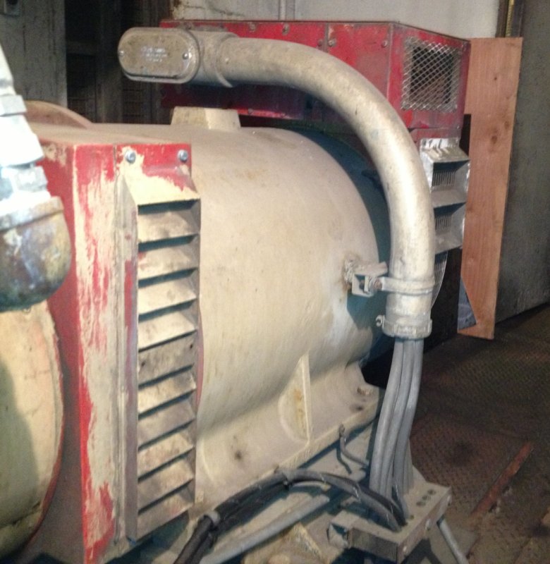
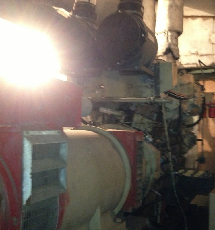
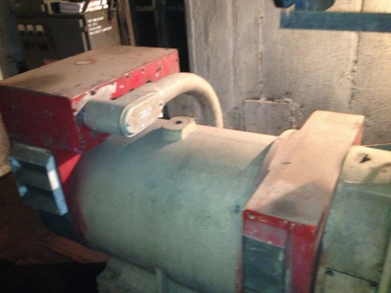
Finally someone (not me) got some pictures for your esteemed review.

I'm still grappling with the 12Vdc field suggestions because with more investigation (but probably not enough) the 125Vdc Basler regulator that was taken out appeared to be the original unit buried deep in the panel bolted into original looking holes etc.

Here's to figuring out if this machine has a coaxial exciter generator:


photo1_qq3l8y.jpg


photo2_mtl8st.jpg


photo3_hwv4sd.jpg


photo5_fyai89.jpg


Still think its a Newage Stamford tailend?

Keith Cress
kcress -
 
That is most certainly a Stamford gen end...can tell by the shape of the fan and bearing housings. The exciter armature will be mounted on the rear of the main rotor. There is no PMG, indicated by the absence of a large protruding cover on the bearing housing.

I am curious as to why the VR902 is being specified as the replacement regulator? Does the customer use this model as a standard replacement? Not that it is necessarily a bad choice, I'm just wondering because there are several regulator models that would work. As Mike said, the AVR specs are just the maximum rated--it doesn't mean the AVR will necessarily ever reach the rated field output in actual operation.
 
Hi Keith;
I suggest hooking up a battery (6 or 12 Volts) as per Mikes suggestion so you can estimate the voltage that you will need out of your regulator.
Are you sure about the need for a shunt trip breaker? I haven't encountered one on a set in that size range.
Comments Mike?
If you have a PMG then 50 VA is adequate for sensing.
BUT, I don't see a PMG fitted. If you must supply both sensing and power to the AVR you may need a larger transformer.
Looking at your first picture, we see the end of the shaft and the Non Drive End bearing. A PMG set will have a short shaft extension past the NDE bearing and the PMG will be mounted there and will cover the NDE bearing. The end of the shaft is not visible with a PMG fitted.

Bill
--------------------
"Why not the best?"
Jimmy Carter
 
Keith,

I agree with what else has been said, if it was my project I would move forward like this,

Open the top cover of the generator, see what the PT and power transformer connections and rating are.

Open the rear side covers/grills, inspect/test the diodes and surge suppressor.

Perform an insulation resistance test on ALL the generator winding (regulators fail by themselves sometimes, mostly they are damaged as the result of another problem, at least in my experience).

Measure and record the field resistance.

Use a 6 or 12 volt battery, hooked up per the Stamford Troubleshooting guide posted before, start and run the unit at rated speed, see what the generator output voltage is. During that test also verify what the output of the power transformer and the sensing transformer is.

After that you should have enough good info to determine exactly what you need in a replacement AVR.

Hope that helps, MikeL
 
Great suggestions Mike. lps

Bill
--------------------
"Why not the best?"
Jimmy Carter
 
Working thru these nice posts and answering as I read them;

IBRCAN; Thanks for the confirmation and the description of the PMG style.

IBRCAN said:
curious as to why the VR902 is being specified as the replacement regulator

A company I'm, not even sure of its name, has helped us with regulators and generator parts before was contacted and asked for a replacement Basler APR125-5. Their response was, "[highlight #8AE234]That Basler is no longer available and Basler has pretty much stopped supplying 'small' regulators in general. Here's the replacement. Make sure you make the changes shown in this instruction sheet.[/highlight]"

The regulator was bought and literally screwed in place before anyone looked at the instruction sheet and decided they didn't know what half the stuff was. They showed up at my place and thrust the instruction sheet and the dead COMPLETELY potted Basler in may hands and said things like, "We've done such and such so far but need help now. What's a potential transformer? What kind of weird breaker is that? Here please deal with it".

Ahhh, what are friends for?

Bill;
Bill said:
Are you sure about the need for a shunt trip breaker?

I can only point you to the instruction sheet. Here it is:

VR902 PDF

Looks like a shunt trip to me... ?


Bill said:
If you must supply both sensing and power to the AVR you may need a larger transformer.

You'll note that the sensing and the excitation are indeed both needed and are NOT supposed to share the phase. The sense is indeed paltry as expected and the excitation needs to be supplied by enough power to do the job - pretty much the point of this entire post - estimating what's needed for the excitation transformer size.

I find it interesting that the Basler didn't apparently need the excitation transformer and had ONLY the:
F-
F+
4- E3
3
480 (E1)
Screws hooked up. That's five wires only.

And thanks Bill for the further details on what a PMG'd generator looks like.


Keith Cress
kcress -
 
MikeL said:
1) Open the top cover of the generator, see what the PT and power transformer connections and rating are.

2) Open the rear side covers/grills, inspect/test the diodes and surge suppressor.

3) Perform an insulation resistance test on ALL the generator winding (regulators fail by themselves sometimes, mostly they are damaged as the result of another problem, at least in my experience).

4) Measure and record the field resistance.

5) Use a 6 or 12 volt battery, hooked up per the Stamford Troubleshooting guide posted before, start and run the unit at rated speed, see what the generator output voltage is. During that test also verify what the output of the power transformer and the sensing transformer is.

Mike, that is indeed a nice punch list for this issue. I will try to set this up. It makes good clear sense that it could certainly be something other than the regulator that caused the reg to fizzle.

I guess I'm going to need to make the trip. :/

Keith Cress
kcress -
 
Keith,

Basler still makes all "small AVR's", but they have reduced the number of distributors they sell thru and a lot of folks who used to be Basler houses no longer are. There are also a ton of Chinese knockoffs for many Basler and other AVR's now.

The VR902 was a fair replacement AVR, as it would provide as much field output as it had input power for, if you use 120 VAC input power it performed like a 63 volt nominal AVR, supply a higher voltage like 277 and it would increase the available output field voltage. Drawback is that is does not have an internal over-excitation limiter, so the need for the shunt trip field breaker.

Based on your pictures it sure looks like an older size 6 frame Stamford, most of those units used MX321 AVR's. I'd be interested to see what you find when you open the top of the generator connection box, most of the ones that vintage I have worked on had an encapsulated transformer with multiple outputs rated at about 1000VA. If you are lucky the old original connection diagram may still be on the underside of the connection box top.

Maybe you should take the day off tomorrow and head over to PowerGen in Vegas, along with Basler there are a number of other suppliers there for AVR's and transformers

MikeL.
 
Status
Not open for further replies.

Part and Inventory Search

Sponsor