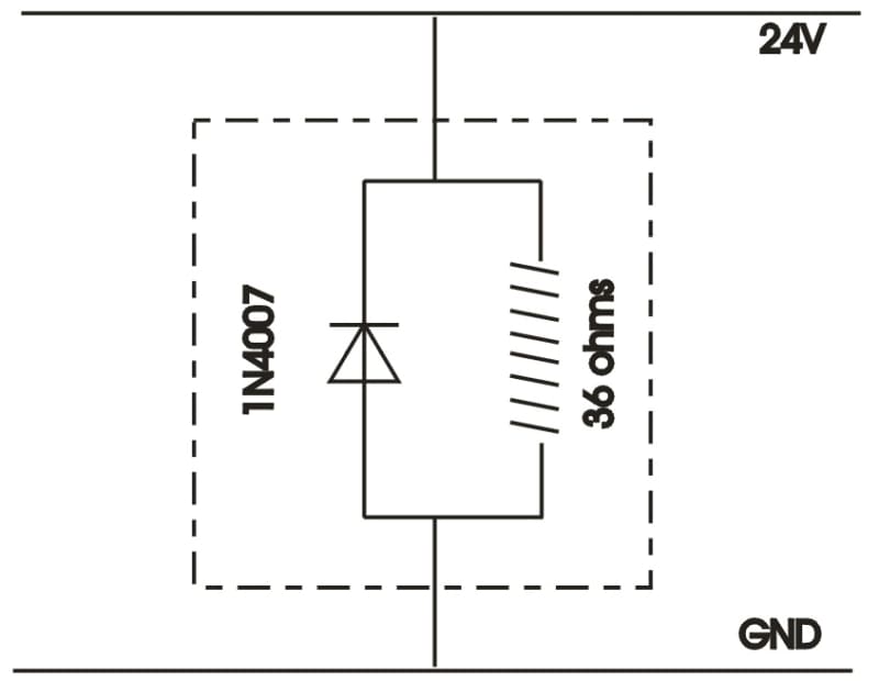
Continue to Site

Eng-Tips is the largest engineering community on the Internet

Intelligent Work Forums for Engineering Professionals

  • Congratulations SSS148 on being selected by the Eng-Tips community for having the most helpful posts in the forums last week. Way to Go!

voltage suppression diode orientation

Status
Not open for further replies.

MRSSPOCK

Mechanical
Aug 29, 2010
303
Let's say, like me, you have wired a voltage suppression diode in parallel with a solenoid coil, but you forgot to label the identical wires before the solenoid got buried under other components, not to mention the adhesive heat shrink. Is there a way to determine the orientation of the diode with basic equipment, with just the two wires coming from the coil / diode assembly? I ended up peeling back the insulation etc to actually see the diode, but I couldn't help but think there must be an easier way to do this. I realise energising the coil briefly while watching the voltage across the coil with an oscilloscope would provide a means to witness if the voltage spike was suppressed or not, but is there a simpler way? It would be so easy to install such a solenoid backwards by mistake, just to have the diode blow immediately, while the coil still remaining functional, but no voltage spikes being suppressed. It would be nice to be able to do a last minute verification, but I can't think how. I will gladly try any suggestions and post the results.
 
Replies continue below

Recommended for you

But with the coil in parallel it is going to conduct in both directions.
 
An interesting question. It would take an unusual amount of equipment to sort that out!

You would use something like a 12 or 24V incandescent light bulb. Hook it in series with one lead. Apply across the combination 12 or 24V AC using a transformer like a door bell transformer. The lamp will limit the current protecting the coil (depending).

Then you look across the coil/diode with a scope. You will clearly see the direction the current is flowing across the diode. It will prefer the diode in the diode conduction direction. That will show the voltage across the coil/diode to be greatly reduced (to 0.7V) in the forward direction. That is the opposite of the direction you'd want the DC system to be applied.

Keith Cress
kcress -
 
@itsmoked. Yes, but like I said, with a scope it is easy. Wire it the wrong way and the transient will be clear to see.

Just to clarify, the image below shows the circuit. The zone inside the dashed line is no longer visible. I just have the two wires to attach to the power rails, but want to confirm diode orientation. By the way this is purely academic since the project is complete, but I thought I must try to figure this out for future application.
diode_orientation_esd2j4.jpg
 
The diode testing function on an ohm meter should work. The forward biased resistance of the diode should be considerably less than the 36 ohms of the coil. In this mode I believe the meter is actually reading the voltage at the probes due to a current supplied by the meter.
 
@Compositepro. This was a few months ago, but from memory I think I tried that. I will have to recreate it now to test it.

I also just had another idea, but maybe someone can predict a flaw in my suggestion as shown below.

The plan is to do the test as shown, then to reverse the multimeter leads.

I'm guessing in the reverse situation the resistance will be greater.

diode_test_opxehj.jpg
 
I'm not sure why this is so complicated. The 1N4007 datasheet makes it pretty clear that it should be trivial to detect the direction of the diode. The 1N4007 has 1000V spec blocking voltage and a maximum of 10 uA reverse current, which means that it will behave like an open circuit at 1V. In the forward direction, the 1N4007 is specified to conduct at least 1A at 1V, which means that it will behave like a 1 ohm resistor. So, 1V applied in one direction, you should get about 28 mA, and in the other direction, you should get 1A.

TTFN (ta ta for now)
I can do absolutely anything. I'm an expert! faq731-376 forum1529 Entire Forum list
 
@ IRstuff Thanks. I knew there had to an easy way. I just couldn't think of it. I'm off to look for my 36ohm coil now to prove it.
 
Ok.

Here goes.

I couldn't find the 36 ohm coil so I used a 5.6 ohm coil instead. (I know I could have used a resistor, but I just wanted to replicate the real case as best I could).

With a 1.59V battery, current with one diode orientation = 1.723A = 0.92 ohms resistance

and when reversed, 0.268A = 5.93 ohms resistance

Perfect.

Thanks again

 
Status
Not open for further replies.

Part and Inventory Search

Sponsor