Eng-Tips is the largest engineering community on the Internet

Intelligent Work Forums for Engineering Professionals

Voltage Suppression for 19H 50A DC Motor Field 3

Status
Not open for further replies.

HenryOhm

Electrical
Jun 22, 2005
58
0
0
US
I have a project involving large 7000Hp DC motors with 19H fields with a resistance of about 5ohm. They normally need around 20-50A of field current for most all operating scenarios. Currently, the system has selenium suppressors installed for overvoltage suppression if the exciter suddenly trips offline. There is also a discharge resistor in parallel of 350ohm and 500W. The selenium suppressors may have failed in some cases and we are looking for logical replacements.

When I take the 50A and 19H for energy stored in a motor field, I get ~24000J. Some of the largest MOV's I see from TDK, Epcos, etc list maybe 10000J but then also have a higher let through or clamping voltage than I'd like. The joule rating of these are for 1.2/100us - 8/50us type transients with really high current spikes. Not sure if the manufacturers would even be able to say what the joule rating for such devices would be in this completely different (current-limited) suppression application.

I also started to look into power avalanche/zener diodes or something similar. But, even in the largest sizes, they didn't seem to have the thermal ratings I might need.

Please don't tell me that the below Siemens product would be the normal solution for the motor fields I'm dealing with(?!):


Thanks!
 
Replies continue below

Recommended for you

If your excitation never changes polarity, then a simple power diode plus power resistor combination will be your best choice. If the decay time isn't important, you can do with a parallel free-wheeling diode alone. A 50 A diode is overkill, but it doesn't cost much to be on the safe side.

Choosing R=10 ohms will give you a modest peak voltage of around 250 V and a 500 or 1000 W wire-wound resistor should be able to absorb and dissipate the 25 kJ without glowing too brightly.

Gunnar Englund
--------------------------------------
Half full - Half empty? I don't mind. It's what in it that counts.
 
Gunnar, much appreciated. Unfortunately, the exciter does reverse its voltage output when online to collapse the field quickly and regenerate back. My initial thought along these lines was to just use two avalanche/zener diodes (a typical cathode connected power diode module with three terminals and I'd only use the two). But, that would obviously depend on a reverse breakdown region rather than forward.

In my initial search, most of the power avalanche diodes did not pass this much current, at least at a typical non-conducting temperature I'd expect for the rarely used application. Related to this, they appeared to have a severe temperature dependence where at the same revere breakdown voltage they might go from 1A to 100A depending on whether they were at 25C or 150C. But, I didn't spend much time looking here and will go down this road further.

Any continuing thoughts along these line or otherwise would be greatly appreciated from anyone....
 
You could look at how the excitation system of a large generator operates. These are typically fully controlled bridges with regenerative capability to actively drive the field, which sounds fairly close to what you have albeit a little larger in scale.

The excitation contactor has two N.O. main poles and two N.C. auxiliary poles adjusted for a make-before-break action. The main poles connect the rectifier to the field winding of the machine, and the auxiliary poles connect a field discharge resistor across the field winding. There's a momentary overlap where the discharge resistor is connected across the rectifier output but this state exists only for milliseconds. Normally a Metrosil voltage-dependent resistor is connected across the rectifier side of the main poles to clamp any switching transients to a non-damaging level, althoug a large MOV might suffice in your application. I might even have a typical schematic somewhere.
 
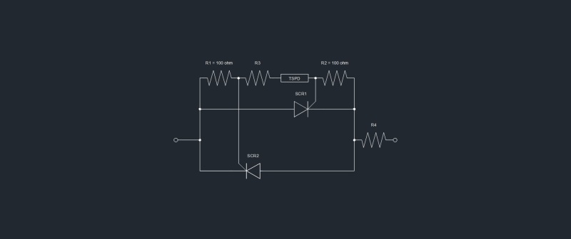
If you want to roll your own poor mans version of that Siemens product then put a pair of SCR's back to back. Use a 100 ohm resistor between the gate and cathode of each SCR and a thyristor surge protection device (TSPD) and resistor in series between the gates. Pick the TSPD Vdrm to be around 1.2 times the peak of the AC supply voltage. The series resistor is to limit the peak gate current to around 1-2A. Put this circuit in series with a power resistor to absorb the energy.
 
ScottyUK,

That's a pretty fascinating (and large!) application. Thanks for sharing that. I wish I could implement something like that at this juncture. But, the selenium suppressors are needing replaced fairly quickly so I obviously was hoping for a less involved solution. Still, it might come into play. For now, we may have to leave the selenium in place and replace with identical that are still (amazingly) on the market.

LionelHutz,

Thanks for the info. The below image file is what I came up with. Please let me know if it looks about right?

thyristor_surge_protection_sbf3w3.jpg


Thanks!
 
Status
Not open for further replies.
Back
Top